Let's take a look at an example of a simple 8-bit counter to learn how to add the IP cores of the ChipScope Pro kernel generator to the project and observe the internal nodes and logic of the FPGA. In this example, we will call an ICON, an ILA, and a VIO.
1. New project engineering and RTL procedures.
(1) New project, select the device model, package and other project information, as shown in Figure 9-14.
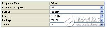
Figure 9-14 Device Model Information
(2) Write or add the source program count_top.v.
Count_top.v
Module count_top(clk, reset
);
Input clk;
Input reset;
Reg [7:0] count_out;
Always @(posedge clk) begin
If (reset == 0)
Count_out <= 0;
Else
Count_out <= count_out + 1;
End
Endmodule
(1) In the ISE environment, click [Project] menu → [New Source], pop up the source program setting interface, select the source program type [IP (Core Generator & Architecture Wizard)], enter the IP core name to be generated, such as ICON_Core, as shown in Figure 9-15.
![[New Source Wizard] Select source program type interface](http://i.bosscdn.com/blog/0H/41/11/462_0.png)
Figure 9-15 [New Source Wizard] Select the source type interface
(2) Click [Next] to pop up the IP list of the kernel generator, select [View By FuncTIon] → [Debug & VerifictaTIon] → [Chipscope Pro] → [ICON (ChipScope Pro-Integrated Controller)], as shown in Figure 9- 16 is shown.
![[New Source Wizard] IP core interface](http://i.bosscdn.com/blog/0H/40/9B/64_0.png)
Figure 9-16 [New Source Wizard] IP core interface
(3) Click [Next] to enter the ICON configuration page. Since this example uses two debug cores ILA and VIO, ICON requires two control ports and sets [Number of Control Ports] to 2. As shown in Figure 9-17.
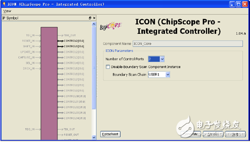
Figure 9-17 ICON configuration page
(4) Click [Generate] to generate the ICON core.
3. Generate an ILA core.(1) Go back to the ISE interface, [Project] → [New Source], pop up the source program setting interface, select [IP (Core Generator & Architecture Wizard)], enter the IP core name to be generated, such as ILA_Core, as shown in Figure 9- 18 is shown.
![[New Source Wizard] Select source program type interface](http://i.bosscdn.com/blog/0H/31/19/555_0.png)
Figure 9-18 [New Source Wizard] Select the source type interface
(2) Click [Next] to enter the IP list of the kernel generator, click [View By FuncTIon] → [Debug & VerifictaTIon] → [Chipscope Pro] → [ILA (ChipScope Pro-Integrated Logic Analyzer)], as shown in the figure 9-19.
![[New Source Wizard] IP core interface](http://i.bosscdn.com/blog/0H/30/42/128_0.png)
Figure 9-19 [New Source Wizard] IP core interface
(3) Click [Next] to bring up the ILA Summary interface, as shown in Figure 9-20.
![[New Source Wizard] Summary interface](http://i.bosscdn.com/blog/0H/14/0K/57_0.png)
Figure 9-20 [New Source Wizard] Summary interface
(4) Click [Finish] to enter the ILA configuration page. Configure the trigger port and storage attributes, as shown in Figure 9-21.
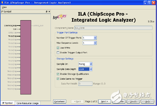
Figure 9-21 ILA attribute interface 1
(5) Click [Next] to enter the ILA configuration page 2 and configure the trigger conditions as shown in Figure 9-22.
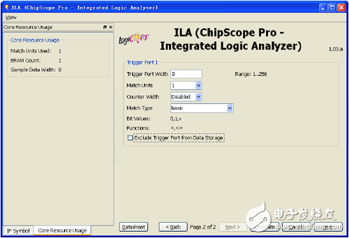
Figure 9-22 ILA property interface 2
RF Coaxial Connector,RF QMA Connector,RF FME Coaxial Cable Connector,Wire Solder Type RF Connectors
Xi'an KNT Scien-tech Co., Ltd , https://www.honorconnector.com