Abstract: High-power LED lamps have many advantages such as energy saving and high efficiency, and they have great development prospects. Their driving and dimming are the hotspots in recent years. Therefore, this paper has carried on the in-depth research on LED street lamps, and designed the driving circuit of LED street lamps for their characteristics. And intelligent dimming circuit, which constitutes the LED street light system.
The drive circuit is a Buck-Boost-Buck circuit controlled by HV9931. It is directly driven by the mains to achieve constant current drive and has PFC function. The dimming mode adopts PWM dimming, and TLS2561 is used as the light intensity sensor. PWM modulation is generated by PIC16C62 control. Optical signal control HV9931 enables intelligent dimming.
The experimental results show that the circuit has high conversion efficiency, high power factor, small THD of input current, pure white light and good energy saving, and has great market prospects and further research value.
1 Introduction
LED is considered to be the fourth generation of green light source. It is a solid cold light source with many advantages such as high efficiency, long life, safety and environmental protection, small size and fast response. It has been used in urban landscape installation, traffic signals and commercial advertising. widely used. In recent years, with the continuous development of manufacturing processes, the performance of high-power high-brightness LEDs has been continuously improved, and the price has been declining. At present, the same obvious effect is achieved. The power consumption of LEDs is about /10 of incandescent lamps and 1 /2 of fluorescent lamps. 2]. These have made it suitable for general lighting, and it has great development prospects. It has a tendency to replace traditional light sources such as incandescent lamps and fluorescent lamps. The application of LED lamps at the World Expo can be said to represent this direction. LED dimming can save energy. The driving and dimming of high-brightness white LEDs is a hot topic in recent years. This paper has done some research in this area, and designed an LED street lamp driver and intelligent dimming system with power factor correction. .
2 LED characteristics, drive requirements and dimming methods
The theoretical light efficiency of LED is 300lm / W. The current laboratory level is 260lm / W, and the market level is above 120lm / W. The high-brightness LED has a typical turn-on voltage of about 3.0 to 4. 3V, but its core is still a PN junction, and its volt-ampere characteristics are the same as those of a normal diode. When the voltage applied to the LED is less than its turn-on voltage, almost no current flows through the LED. However, when the LED is turned on, its forward current changes exponentially with the forward voltage, and a small voltage fluctuation causes a large current change. When the voltage in the conduction region rises from 80% of the rated value to 100%, the current rises from 0% of its rated value to 100%.
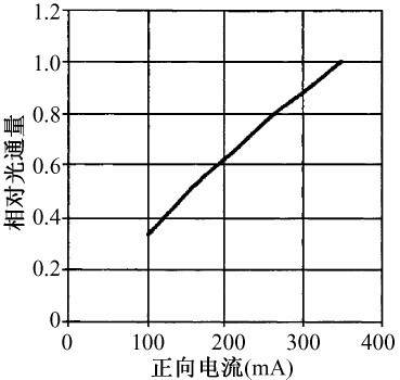
Figure 1 LED relative luminous flux and forward current relationship
Figure 1 is a plot of LED relative luminous flux and its forward current IF. It can be seen that the luminous flux of the LED is proportional to its forward current, so it is possible to control the luminance of the LED by controlling the forward current of the LED. If the LED is driven by a constant voltage source, a small voltage change will cause a large current change, so the constant voltage drive is only suitable for low power requirements. In high-demand applications and high-power applications, LEDs must be driven with constant current. Research shows that the brightness of LED light decreases with the working time. After the brightness decreases, the light effect decreases with the increase of current, and the brightness of LED is saturated with the driving current. After the current of the LED reaches 70% ~ 80% of its rated current, a large proportion of the current is converted into thermal energy, so the driving current of the LED should be 70% ~ 80% of the rated current of the working current. In constant voltage drive or PWM dimming, the maximum current should not exceed 3 times of the minimum current. Otherwise, the inrush current will greatly reduce the service life of the LED [8]. At present, the power of market-oriented single LED is not large, mostly in Below 10W, the actual use for illumination is to form a LED array by placing a plurality of LEDs in parallel or in series.
It can also be seen from Figure 1 that changing the LED current changes the brightness of the LED. There are two ways to change the current, and there are two ways to divert the corresponding LED. One is to continuously adjust the current in the LED to change the brightness of the LED. This method is called analog dimming, and the current through the LED is continuous. The other is to change the time and turn-off of the LED current. The ratio of time to change the brightness of the LED, the current is constant when the LED flows through the current, and the current flowing through the LED when it is turned off is zero. This method is called PWM dimming, which is a frequency that is not noticeable by the human eye. Fast switching LED, the switching frequency should be no less than 100Hz. The two dimming methods have the same effect when the average current flowing through the LED is the same. Since the LED emits the purest white light at a certain current of a certain size, there is a color shift as the current deviates from this value. In addition, the response time of LEDs is only a few nanoseconds to tens of nanoseconds, which is suitable for frequent switching applications, so LED dimming is better with PWM dimming, and this method is also beneficial for LED heat dissipation.
3 LED drive circuit
3. 1 LED drive circuit classification
The driving power of the LED can be divided into AC / DC type and DC / DC type, and the LED requires DC power supply. When AC power is supplied, the AC is converted into DC and then the LED is driven. Therefore, we only need to study the DC / DC type. can. The DC/DC type LED can be divided into a resistor current limiting type, a linear regulated power supply type, a capacitor charge pump circuit and an inductive switching converter circuit. The resistor current limiting connects the resistor and the LED in series, and divides the current through the resistor to limit the current and drive the LED lamp. In this way, the control accuracy cannot be guaranteed, and a large amount of electric power is wasted on the resistor, and is only used in a low voltage occasion where the requirement is not high. The accuracy of the linear regulated power supply is higher than that of the resistor current limiting type, but there are also problems of low efficiency, and there are not many used in practice. More practically used are charge pump circuits and inductive switching converter circuits.
The charge pump circuit uses the cumulative effect of the capacitance on the charge to store the electrical energy, and the capacitive action energy coupling element is switched by controlling the high frequency switch of the power electronic device to allow the capacitor to store energy during a part of the clock cycle for the remainder of the clock cycle. The internal capacitor releases energy. In this way, different output voltages are obtained by different connections of the capacitor during charging and discharging. The inductive switch conversion circuit, also known as the switching power supply, changes the output voltage by controlling the time relationship between the on and off of the power switch tube. The inductor and the capacitor are generally used as filter elements to stabilize the output. In comparison, the charge pump type uses fewer components, lower cost, and smaller size, but it uses more switching components, and the efficiency is relatively lower. The output voltage is in the range of 1/3 to 3 times of the input voltage, and the output power is small. Therefore, it is often used in low-power applications; and switching power supply switching components are relatively few, high efficiency, can achieve a wide range of voltage output, and the output voltage is continuously adjustable, the output power is large, so the scope of application is wider, especially in the middle High power is the first choice. There are many topologies for switching power supplies, and Boost circuits, Buck-Boost and Buck circuits are used in LED driver circuits.
3. 2 HV9931 based LED street light drive circuit design
There are already some LED-driven chips available. LED street lamps are relatively powerful, and are powered by mains AC. According to the state regulations, power factor correction devices are required when the power reaches a certain value. In addition, LED street lamps designed to have dimming function to save energy. Based on the above considerations, Supertex's HV9931 function driver chip is used here. The HV9931 is an 8-pin PWM integrated controller with the following functions and features: (1) Constant output current for LED constant current driving; (2) Wide range of DC input voltages for a wide range of 8 ~ 450V And there is a large step-down ratio, so the utility model can be used to drive the LED lamp without the transformer; (3) With the power factor correction function, the unit power factor and the low input current harmonic can be obtained, which meets the national regulations and is environmentally friendly; (4) With PWM dimming and analog dimming function, it can easily realize dimming control when driving LED, which meets energy saving requirements; (5) The oscillator has two working modes: fixed frequency and fixed off time.
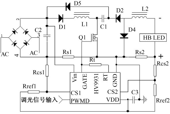
Figure 2 LED street light driver circuit based on HV9931
The drive circuit is shown in Figure 2, which is the switching power supply drive mode.
The main circuit is a single-stage, single-switch, non-isolated constant-current output Buck-Boost-Buck circuit. The Buck-Boost circuit consisting of L1, C1, D1, D5 and Q1 is the input stage and operates in discontinuous conduction mode. The Buck circuit consisting of C1, Q1, D2, D4 and L2 is the output stage and operates in continuous conduction mode. under. The two stages share one power switch tube Q1, the capacitor C1 is equivalent to the load to the input stage, and the output stage is equivalent to the DC power supply. The system step-down ratio is the product of the two-stage step-down ratio, so that the mains supply does not require a transformer to achieve a lower voltage output. When the switch Q1 is turned on, the input stage Buck-Boos current path: rectified voltage → D1 → L1 → Q1 → Rs1, the current in L1 increases linearly, and the current path of the output stage Buck circuit is:
C1→Q1→Rs2→LED→L2, C1 provides energy; when Q1 is off, the input stage current path: L1→C1→D5→D1, the energy in L1 is transferred to C1, and the L1 current cannot be reversed due to the existence of D1 , L1 current drop to 0 after the current is interrupted; output stage current path: L2 → D4 → LED, due to different parameter settings, the current in L2 will not not become 0, and the fluctuation is relatively small.
When the circuit is operating in peak current mode, the oscillator causes GATE to output a high level to turn Q1 on; the CS1 and CS2 terminals are the inverting inputs of the two voltage comparators inside the HV9931, and the two comparators are in the same direction. The input terminal is grounded inside the chip, and the circuit detects the input current and output current through the CS1 and CS2 terminals simultaneously. CS1 is the input current signal detection terminal, and CS2 outputs the current signal detection terminal. The voltage of these two terminals is lower than the ground. The GATE terminal outputs a low level and Q1 turns off. VDD is the reference voltage output pin of the chip, Rs1, Rcs1 and Rref1 can be programmed to set the maximum peak current in L1, and Rs2, Rcs2 and Rref2 can be programmed to set the output current. The duty cycle and the switching frequency are considered to be constant during the period of the alternating current, so the input current peak envelope is a sine wave, and the average current is a sine wave, which can be corrected by the power factor.
C2 is the input capacitor and is used as a high frequency bypass. If a large capacitor is used, the circuit loses power factor correction. RT corresponds to the internal oscillator. There are two ways to set the constant operating frequency and the constant off time. The figure uses a constant turn-off time connection. The PWMD pin is a digital dimming signal input pin. When the pin is high, the circuit works normally. When the pin is low, the GATE pin always outputs a low level, the switch Q1 is off, and the drive circuit does not work.
4 intelligent dimming device
If the designed system can change its brightness according to the intensity of the ambient light, it will save energy and meet the current requirements of low carbon life. When the ambient light is the worst, the PWM duty cycle of the design system dimming signal is close to 100% (in order not to make the temperature rise too high, leaving a certain margin), the LED is the brightest to meet the illumination requirement; when the ambient light changes, it will be based on the external The intensity of the light automatically changes the duty cycle of the PWM of the dimming signal, so that the LED is correspondingly darker, but the illumination meets the requirements; in addition, the brightness can be appropriately reduced when there are few people in the middle of the night.
A good light intensity sensor is required to achieve this. The photoresistor has poor linearity, low frequency response, and high sensitivity of the phototransistor. However, the temperature characteristics and linearity difference system design use TLS2561 as the photoelectric intensity sensor. TLS2561 is close to the human eye's response to brightness. It can directly convert the light intensity signal into a digital signal output. It has a programmable interrupt function and a standard I 2 C interface, which can be easily connected to the microcontroller. The MCU selects PIC16C62 of Microchip, which has stable performance and PWM output, which can easily realize I 2 C bus communication. The light intensity sensor TLS2561 converts the optical signal into a digital signal and transmits it to the single chip microcomputer. The PWM signal is generated by the single chip processing, and the dimming PWM signal is sent to the PWMD end of the HV9931 to realize PWM dimming. The dimming section is shown in Figure 3.

Figure 3 Dimming system block diagram
The system is also designed to take into account the effects of temperature. At the same current, the LED will decrease as the PN junction temperature increases, and it will also affect the LED's lifetime. Therefore, the temperature sensor added to the system, the temperature signal is also sent to the PIC16C62 processing, it will also affect the duty cycle of the PWM dimming signal output. This is not the main problem of this design, it is not described in detail.
5 Experimental results
The system design power is 72W, and 72 1W high-brightness LED lamps are connected in parallel after 24 series. When the maximum light intensity is output, the duty ratio of the PWM dimming signal is 90%. At this time, the average value of the total current in the LED is 932mA. When the LED driving circuit is working, the operating frequency of the switching tube is 100kHz, and the driving circuit efficiency is 75%. The current THD is less than 20%, the power factor is greater than 0. 9, the photoelectric conversion efficiency is about 95lm / W; the dimming PWM signal frequency is 120Hz, which is about 9% energy saving when not using the intelligent dimming circuit. Figure 4 shows the dimming PWM Current waveform in the LED at 50% duty cycle.
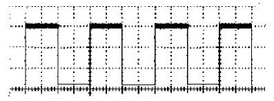
Figure 4 Current waveform in the LED when the dimming PWM duty cycle is 50%
6 Conclusion
The LED street lamp driving circuit designed in this paper adopts the mains power supply and does not need the power transformer, and the drive circuit volume is greatly reduced. The drive circuit realizes constant current drive with PFC function, which meets the requirements of current green environmental protection, and the drive circuit has high conversion efficiency and novel circuit; the intelligent dimming circuit adopts PWM dimming mode, and the LED emits relatively pure white light, which does not generate Color shift. The energy saving effect of the intelligent dimming circuit is more significant. The actual circuit of the design has a good prospect and market. The disadvantage is that the cost is slightly higher. However, with the continuous improvement of the LED manufacturing process and the continuous research of the driving dimming circuit, it is believed that this problem will be well solved.

Noah S Led Grow Light,3 Dimmers Noah S Series Led Grow Light,Noah S 5W Led Grow Light,Noah S Series Chip Led Grow Light
Shenzhen Mingxue Optoelectronics CO.,Ltd , https://www.led-lamp-china.com