This article refers to the address: http://
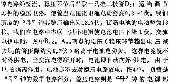
Minute. B18, A20 is the schematic diagram of the digital electronic clock in Figure 2 corresponding to the "Electric World", No. 6, 1983, No. 6, pp. 40, which means that the positive pole of the printed circuit board C8 of the master clock is disconnected from the 4 feet of J1. D2 in Figure 4. The capacitor C is connected in parallel across the load to prevent the second pulse from being lost during power conversion.
Cctv Power Adapter,Ac Dc Power Adapter,Fiber Flange Fly Power Adapter,Cctv Camera Power Adapter
Ninghai Yingjiao Electrical Co., Ltd. , https://www.yingjiaoadapter.com