Abstract: Automobile rear-end warning is an important research content in intelligent vehicle visual navigation system. An automobile rear-end warning system based on monocular vision is designed for use in a structured road environment. According to the road image sequence provided by the camera, the system first uses a new edge detection algorithm to identify the road ahead, and then uses the features of gray, edge and symmetry to identify the vehicle in front, and then judges the threat level based on the front and rear distances. Provide the driver with the corresponding audible and visual alarm signal. The system has been tested on the highway in Hefei. The experimental results show that the system running speed meets the real-time requirements of vehicle driving, and can complete the tasks of vehicle detection and collision warning.
Keywords: vehicle detection; collision warning; monocular vision; intelligent vehicle
0 Introduction Highway anti-collision system based on computer vision is one of the hotspots of current intelligent traffic management system research. How to quickly and accurately detect lanes and vehicles from video images in a changing environment is the most critical issue for implementing such systems. In the past 20 years, many researchers at home and abroad have done a lot of research on this issue, and have proposed a variety of practical algorithms and successfully developed some visual systems. The algorithms employed by these systems can be basically divided into binocular vision based methods, motion based methods, shape based methods, and knowledge based methods. The method based on binocular stereo vision is computationally intensive and requires special hardware support. Based on the motion method, it is impossible to detect stationary targets and the real-time performance is poor. Based on the shape-based method, it is still a problem to be studied because of establishing effective training samples; knowledge-based The method is more efficient when the number of obstacles is small, but the error rate increases in complex environments.
Aiming at the deficiencies of the conventional algorithm, this paper designs a vehicle-mounted rear-end warning system based on monocular vision with high precision and good stability. It uses a new edge detection algorithm to identify the road ahead, and then uses the combination of shadow detection and tracking to identify the vehicle in front. Then it judges the threat level based on the front and rear distances, and finally provides the corresponding sound and light alarm signal to the driver.
1 System working principle The system hardware part includes MCC-4060 CCD camera, VT-121 video capture card, GPS, PC-104 industrial computer and display terminal. The GPS transmits the vehicle speed information to the industrial computer through the serial port. The CCD camera installed in the windshield of the vehicle sends the image frame to the industrial computer through the video capture card. After the software analyzes and analyzes, the front vehicle obstacle is marked on the display terminal. The object and the road marking, at the same time according to the speed, spacing and other judgment of the hazard level, the corresponding sound and light alarm signal;
The software part of the system includes modules for road detection, road tracking, vehicle detection, vehicle tracking, ranging, decision making and alarms. When the vehicle speed reaches 60km/h, the system begins to process the sequence of images acquired in real time. For each frame of image, the lane white line in the image is first detected and tracked, and then the vehicle is detected within the lane-determined region of interest. If there is a suspected obstacle vehicle, start vehicle tracking and use tracking information to further eliminate false alarms. After achieving stable tracking of the obstacle vehicle, the two vehicle spacing and relative motion speed are estimated, the threat level is determined, and a corresponding alarm signal is issued.
2 system key technology
2.1 Road Detection At present, the lane line detection algorithm is mainly suitable for environments with sufficient lighting. Because of the large contrast between the lane line and the road surface, it is easy to obtain clear lane contour information by using various conventional edge detection operators, then select appropriate thresholds to binarize the image, and finally use Hough transform to identify the lane line. However, in a complex lighting environment, the image is subject to various light direct reflections and multiple reflections of objects to form stray light. The image intensity does not reflect the sudden nature of the lane itself, resulting in the inability to correctly detect the lane.
The system adopts a lane detection algorithm that uses the optical density difference to obtain the difference between the lane marking and the road surface reflectivity, and then performs nonlinear edge detection and then Hough transform. This algorithm can effectively solve the lane detection under complex lighting conditions, and can also be used for lane detection at night.
In addition, the tracking research of the current lane line mainly uses the fixed area method or the Kalman filtering method to divide the region of interest according to the result of the previous frame lane detection to track the lane line in real time. However, the fixed region method has a large dependence on the correlation of two frames, and the region of interest is large and the real-time performance is poor. The Kalman filtering method divides the region of interest small, which is easy to generate detection error, and the tracking error is accumulated, and the tracking accuracy is not high. . Therefore, the system uses a new method of dividing the region of interest by combining the fixed area method and the KaIman filtering method when tracking the lane line.
Generally speaking, only the area below the intersection of the lane boundary line (ie, the vanishing point) and the area between the 2 lane lines is taken as the region of interest. Considering that the vehicle traveling across the road is still threatening to the vehicle, the algorithm divides the two lane lines to two. The side is translated by 40 pixels, extending the region of interest to a range that can cover the cross-track vehicle.
2.2 Vehicle detection image contains objects in a large field of view in front of the vehicle, such as roads, trees, guardrails, signs and other vehicles. It is a difficult task to accurately detect the vehicle ahead, and the vehicle detection module of this paper will The setting parameters are automatically changed according to the image background to adapt to changing road scenes and lighting conditions.
To achieve rapid detection of the vehicle, it is first necessary to perform preliminary detection according to the basic characteristics of the vehicle, extract all possible suspected vehicle areas from the image, and then filter and exclude the suspected areas according to other characteristics.
2.2.1 Initial Vehicle Detection The initial inspection features a vehicle shadow, that is, an area at the bottom of the target vehicle with a grayscale value that is significantly lower than the nearby road surface area. Most vehicles have this remarkable feature under normal environmental conditions.
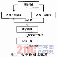
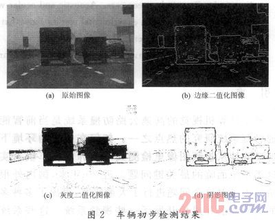
The process of vehicle initial inspection is shown in Figure 1. The vehicle shadow has the same characteristics as the gray level mutation, so the lane detection algorithm can be called to binarize the original image in Fig. 2(a) to obtain the edge binarized image in Fig. 2(b). At the same time, the original image is subjected to gray binarization to obtain the gray binarized image in Fig. 2(c). In order to improve the real-time detection, the average gray level of the road surface area near the vehicle is used as the binarization threshold. Since both the edge binarized image and the gray binarized image include the lower rim of the vehicle, the two images are ORed to obtain a vehicle shadow image as shown in Fig. 2(d).
This article refers to the address: http://
In the shadow image, the line-by-line search is performed from bottom to top, and a line segment in which the continuous shadow point exceeds a certain threshold is found, and a rectangular area is drawn as the bottom side of the line segment as the suspected vehicle area. To ensure that the suspected area contains the vehicle as a whole, the width of the rectangle is slightly wider than the line segment, and the height is given proportionally by the width. To avoid repeated searches, the shadows in the suspected areas that have been searched are completely erased. Since the various parts of the same vehicle may be detected as suspected targets, respectively, it is also necessary to merge the intersecting suspected areas. Due to the occlusion of the vehicle in front, multiple targets may be identified as one target, but have no effect on the safety of the vehicle.
2.2.2 Screening verification If the shadow detection is used for vehicle detection, the low “missing alarm†rate is guaranteed, and the high “false alarm†rate is also generated. Therefore, the suspected area needs to be filtered and verified. .
For structured roads, the ratio of vehicle width to lane width should be approximately fixed. When the parameters such as focal length and pitch angle of the camera are fixed, the lane width (number of pixels) and vehicle width (number of pixels) on the image also satisfy this ratio. . According to the previously detected lane equation, the range of the vehicle image width on any ordinate in the region of interest can be calculated, and the suspected region whose width is not within the range can be eliminated.
In the past vehicle verification methods, the most commonly used symmetry measurement verification. The calculation of this kind of algorithm is large, and for the background is complex, the verification effect of the image with poor symmetry is not satisfactory. To solve this problem, the system uses an algorithm based on edge binarized images to verify the left and right edges of the vehicle.
Suppose the width of the suspected area is W, the coordinates of the left edge of the area are (X1, Y1), and the horizontal coordinates of the right edge are (X2, Y2). Define the function: 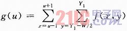
Where: f(x, y) is the gray value of the (x, y) point. Search for the maximum point of g(u) in the interval (X1-W/4, X1+W/4), and the horizontal coordinate X1' corresponding to the point is the left edge coordinate of the vehicle. Similarly, the right edge X2' of the vehicle can be searched. If the g(u) values ​​of the left and right edges are both greater than a certain threshold, then it can be assumed that the vehicle does exist. Experiments show that the algorithm can eliminate a large number of "false alarm" areas and get the sides of the real vehicle.
2.3 Vehicle tracking is concerned with the two-dimensional position and speed of the preceding vehicle and the vehicle. Therefore, it is only necessary to use the Kalman filter to predict the four states of the abscissa x, the lateral velocity Vx, the ordinate y, and the longitudinal coordinate Vy. vector. In addition, since the state vectors of the x direction and the y direction are not directly related, they can be divided into two groups for processing separately.
During the running of the vehicle, due to bumps or occlusions, the system may mistake the road signs, bushes and other objects for the vehicle to detect and generate false alarms. These false alarm objects can only exist in consecutive frames of images. If no action is taken, the system will often generate a short alarm.
When the image sampling interval is short enough, the position of the same vehicle in adjacent frames will have a large correlation.
The system uses the combination of detection and tracking to predict the position of the vehicle in the n+1th frame image based on the information obtained from the image of the nth frame, and compares it with the actually detected result in the n+1 frame image. . If the matching degree of the two is the largest and exceeds a certain value, it is determined to be the same vehicle, and tracking and alarming will continue. Otherwise, the car is considered to be occluded or disappeared, and is temporarily not processed, and is removed after several frames.
2.4 Ranging alarm workshop Ranging usually adopts geometric projection model, adopting a simplified formula of vehicle distance model L×W=C, where L is the distance between two vehicles, the unit is m; W is the lane of the target vehicle on the image. Width, in pixels; C is a constant, which can be obtained by prior calibration. However, the safety distance between the two workshops is dynamically obtained by using the critical safety distance formula derived from the literature. ![]()
In the formula: Vr is the relative vehicle speed, which is obtained by Kalman filtering after obtaining the relative vehicle speed for the measured vehicle distance; Vb is the vehicle speed and is obtained by GPS.
If the alarm frequency is too high, it is easy for the driver to be bothered. If the alarm is too low, the driver may not be able to respond. Therefore, the system uses three alarms from far to near.
If the distance d≥1.5S, it is judged to be a 3-level threat, and a long and slow alarm sound is issued to remind the driver that there is an obstacle in front, but there is no danger at present; if the distance S≤d≤1.5S, the judgment is 2 Level threat, issuing a more urgent alarm sound to remind the driver to decelerate; if the vehicle distance d ≤ S, it is judged to be a level 1 threat, and a short and urgent alarm sound is issued to remind the driver to brake; the difference of the alarm sounds in the three states Very large, the driver can easily judge the threat level based on the alarm sound.
3 Test Results The system framework and all algorithms were compiled in the Boiland C++ Builder 6 environment. In order to verify the reliability and real-time performance of the system algorithm, a large number of experiments were carried out by collecting multiple road images of different models, different sections and different ambient light as test sequences on the Hecheng City Ring Expressway.
Figure 3 shows the experimental results in a typical road scene, Figure 3 (a) is a large truck; (b) is a small van; (c) is a long distance; (d) is a close-range test. The system marks the detected targets with black boxes.
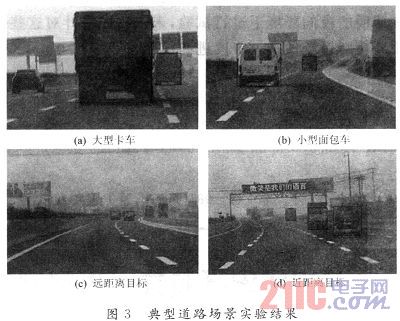
It can be seen that the system is able to detect vehicles of various types at different distances within the lane. Experimental results on the highway show that at a maximum speed of 100 km/h, the processing speed of the system on the Celeron M 600 MHz processor is about 8 j/s, which means that the vehicle is processed within one frame of image time. Driving 3 ~ 4 m, basically meet the requirements of real-time alarm. Under normal lighting conditions, the system's normal alarm longitudinal distance exceeds 200 m, and the field of view is much larger than the radar (typically ±7°).
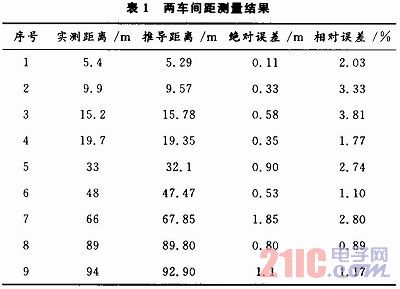
In order to verify the accuracy of monocular vision ranging, a set of images of the front vehicle and the vehicle from 5 to 100 m were collected on the city road. After processing the acquired image, according to the formula, the distance between the vehicle and the preceding vehicle and the actual distance are shown in Table 1. The data in the table shows that the relative error of monocular vision ranging is within 5%, which can meet the needs of ranging warning in actual work.
4 Conclusion This paper designed a car rear-end warning system based on monocular vision. The system adopts a road detection algorithm based on optical density difference, and uses a vehicle detection method based on vehicle shadow detection and auxiliary left and right edge detection. At the same time, a simple and practical ranging and alarm method is adopted. The experimental results on the highway prove the real-time, robustness and accuracy of the system. The system has not been tested in rainy or foggy weather or nighttime environments where there is no lighting. In the future, we will further improve and optimize the system for these environments.
150W 12v 24v Triac Dimmable LED Driver,use the smaller size than the market,better for shipping and installation,Suitable for leading edge and trailing edge dimmers,Waterproof IP65 Aluminum housing series, 1-300W CE/ROHS/SAA/ETL/TUV/EMC,Input voltage can be both 110V and 220V,Wattage can be 1-80W, DALI/TRIAC/0-10V/PUSH dimmable and non dimmable, flicker free,noise free,load free, Perfect dimming curve, PF>0.95,constant current 350mA 700mA 900mA 1200mA,constant voltage 12V 24V 36V, parameters can be customization,OEM/ODM is supported,Same appearances but different sizes, forming a perfect product line,Use for led panel light,led strip light and other indoor led lights
150W led driver/IP65 dimmable driver/Waterproof dimmable driver/IP65 triac dimmable led driver/12v 24v triac dimmable led driver/150W 12v 24v led driver
HAURUI LIGHTING CO.,LTD , http://www.huaruileddriver.com