Energy conservation is a fundamental national policy in China. The government has established a special medium- and long-term energy-saving plan, with the motor system energy-saving project being one of the key focuses. Therefore, reducing energy consumption and improving production efficiency has become a top priority for enterprises. Two main approaches are commonly used: reducing starting current and implementing reactive power compensation to achieve energy savings. Among these, the most effective method for lowering starting current is using variable frequency speed control or soft start technology. Although the cost of frequency conversion equipment has decreased, it remains relatively expensive compared to soft starters. In many cases, choosing a soft starter is more economical, which is why it has been widely adopted. This article introduces the DWR series energy-saving soft starter, highlighting its features, working principles, installation, and usage.
Features
The new DWR series energy-saving soft starter utilizes advanced digital circuit technology, ensuring greater stability and reliability. The main circuit is equipped with high-voltage power devices that provide strong resistance to overvoltage and overload conditions. It supports frequent start-stop operations without causing arc phenomena, thus extending the lifespan of the equipment. Key features include:
- Energy saving, smooth start, no impact on the power grid or equipment, reducing distribution capacity and enhancing productivity.
- No phase sequence requirements during installation, though phase sequence protection can be set as needed.
- Starting voltage ranges from 0 to 80%, and starting time can be adjusted between 2 to 60 seconds.
- Multiple start modes available: ramp voltage start, ramp voltage plus kick start, and ramp voltage plus current limit start.
- Comprehensive protection functions, including fault diagnosis, shutdown for phase failure, three-phase imbalance, overcurrent, overheating, overvoltage, and undervoltage.
- Flexible stop options: free stop or soft stop, with soft stop helping to prevent pressure shocks in high-rise water supply systems.
- Control circuits use industrial single-chip microcomputers with photoelectric isolation and digital structure, offering strong anti-interference capabilities for harsh environments.
- High reliability, long service life, low failure rate, and reduced maintenance costs.
Working Principle
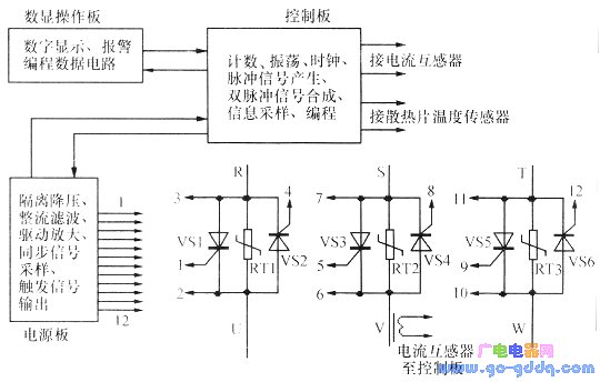
The principle block diagram is shown above. The soft starter consists of three circuit boards and the main circuit. The three-phase 380V power supply is stepped down through an isolation transformer on the power board, then rectified by a three-phase bridge rectifier. The filtered DC power supplies the power board, control board, and digital display board, while also providing a synchronous signal for the control board. The power board provides 8V low-voltage power, which is rectified and used to trigger thyristors based on signals from the control board. This allows adjustment of the thyristor conduction angle to regulate voltage. The control board includes a STC89C52 industrial microcontroller, optocouplers, resistors, capacitors, and integrated circuits, supporting functions like rectification, filtering, counting, oscillation, clock generation, pulse signal creation, and double-pulse synthesis. The digital display panel provides programming signals and displays data. The main circuit contains six high-power thyristors (or MTC-type modules), temperature sensors, varistors, and current transformers. Varistors RT1, RT2, and RT3 help absorb voltage spikes in the main circuit.
Kit Installation
The energy-saving soft starter kit includes a central controller and the main circuit. The central controller houses all control components, including the digital display panel, control board, and power board. The connection between the controller and the main circuit is illustrated in the figure. The main circuit comes in two types: modular and discrete. This article focuses on the modular type. When selecting MTC-type modules, ensure a withstand voltage of 1400V, with at least 3000V between the heat sink and electrode. Module and heat sink selection should be calculated based on motor power, typically using a coefficient of 4 (motor power in kW × 4 = module current). For example, 15–37KW motors may use SRX-CCK size (330×287×30mm), 40–75KW use SRX-CEH (365×230×26mm), and 90–160KW use SRX-CHI (475×301×52mm). Heat sinks should be milled and black-plated. Apply insulating thermal grease when installing the module to ensure good contact and even pressure.
If one motor drives three loads, the thyristor rating can be increased by one level, while the heat sink size remains unchanged. For detailed installation steps, refer to the main circuit section of the user manual.
Function Setting
Factory settings are pre-programmed, allowing direct use. If adjustments are needed, press the setting button, refer to the function code table in the manual, and use the plus/minus keys to adjust values. Press Enter to confirm the changes.
Usage
To use the soft starter, connect the R, S, T terminals to a 380V power supply and the U, V, W terminals to the load. Replace the load with a 220V/200W bulb (Y-connected) for testing. Press the start button; the bulb should gradually brighten. Ensure all bulbs have the same brightness and measure the output voltage to match the input. After confirming everything is normal, disconnect the power and replace the bulb with the actual motor. Adjust the starting voltage and time based on the load. For no-load operation, set the starting voltage to around 10% and the start time to approximately 10 seconds.
Flat Single Axis Solar Tracker System
Flat Single Axis Solar Tracker System,Single Axis Solar Tracker System,Single Axis Solar Tracker System customization
Hebei Jinbiao Construction Materials Tech Corp., Ltd. , https://www.pvcarportsystem.com