The three-step process for activating the alarm function is simple and user-friendly.
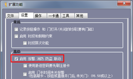
1. Enable the anti-theft alarm function:
- Click on [Tools].
- Select [Extended Function], enter the code 5678, and click [OK].
- Enable the [Alarm, Fire, Anti-Theft, Linkage] function.
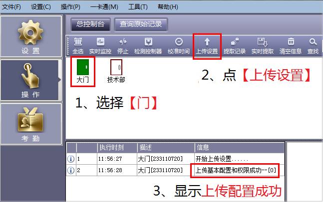
2. Software configuration:
- Go to [Software Settings] and adjust the parameters as needed.
- Upload the settings to ensure they are applied correctly.

**Notes:**
- The [Gate Left Open Long Time Alarm] and [Forced Intrusion] functions require a magnetic signal connection.
- The duress password can be customized; the default is 889988.
- When using the [Swipe + Password Open] feature, entering the duress password after swiping allows you to track who triggered the alarm.
- The time for the [Door Left Open Long Time Alarm] can be adjusted (1–6000 seconds), with a default of 25 seconds.
- The alarm hold time can also be set (0–6553 seconds), with a default of 10 seconds.
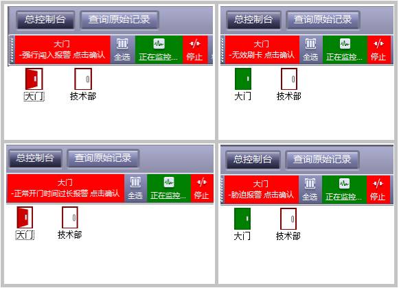
3. Real-time alarm display in the software:
- Once the alarm is triggered, the software will alert and activate the computer’s speaker.
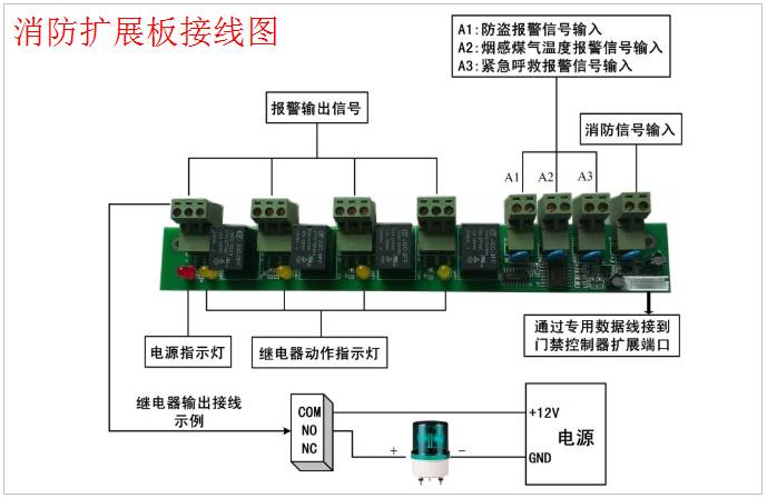
### Three Steps to Understand the Use of the Fire Linkage Expansion Board
1. Locate the fire expansion board within the network.
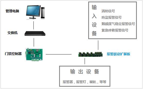
2. Wiring diagram of the fire expansion board:
- Refer to the wiring schematic for proper installation.
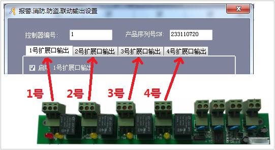
3. Correspondence between the fire expansion board and the software:
- Ensure that the board is properly connected and recognized by the system.
### Software Configuration Method:
- Open the [Burglar Alarm] function.
- Enter [Alarm, Fire, Anti-Theft, Linkage Output Settings] and make your adjustments.
- Save the settings and go to [Total Console] to upload them.
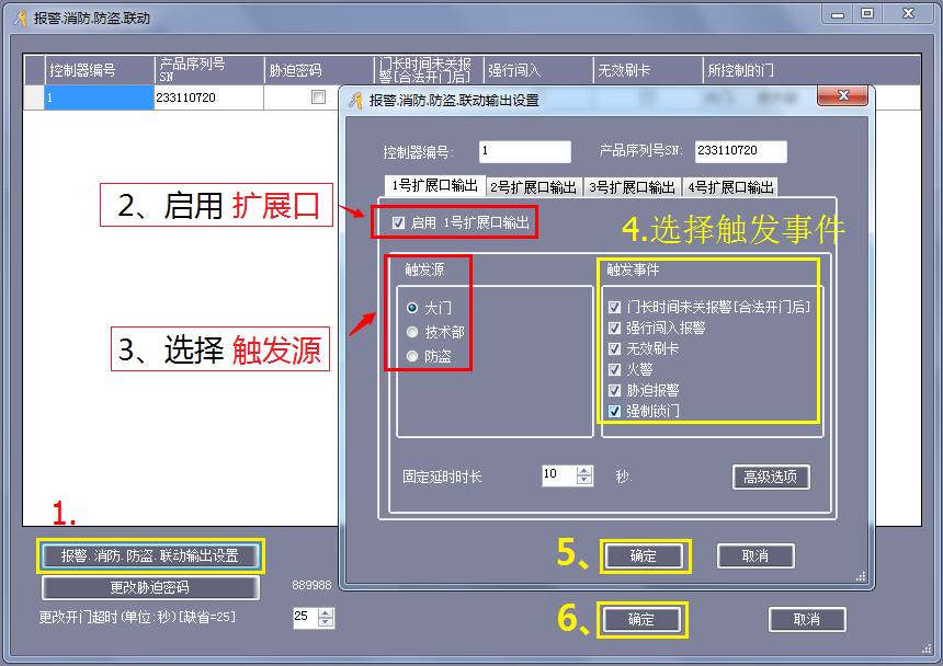
### Summary of Events That Can Trigger an Alarm:
1. Invalid access card.
2. Door left open for too long after being opened legally.
3. Forced entry detected.
4. Duress alarm triggered.
5. Forced lock attempt.
6. Fire alarm activated.
**Note:** These advanced features are available only on the top three professional brands.
### Features Available:
1. Infrared, magnetic door sensors, fortification, disarming, and anti-theft alarms.
2. Smoke and gas detection.
3. Temperature anomaly alerts.
4. Emergency help requests.
### Explanation of the Anti-Theft Alarm Function:
**Prerequisites:**
- The alarm can only be armed or disarmed at Gate 1.
- The LED line of the No. 1 door reader must be connected.
**Procedure:**
- To arm the system: Swipe a valid card three times continuously. The indicator on the No. 1 door reader should flash rapidly. Wait 25 seconds; the light will then flash once every two seconds.
- To disarm: Swipe a valid card three times within 25 seconds after opening the door.
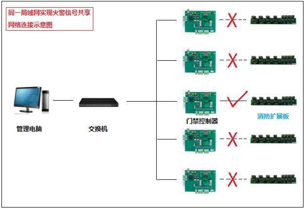
### Fire Alarm Signal Sharing:
If multiple controllers are used, you can share the fire alarm signal across all devices through one expansion board.
**Important Notes:**
- All controllers involved must be on the same LAN.
- A stable and good network environment is essential for this functionality.
### Software Operation for Fire Alarm Signal Sharing:
1. Configure the settings in the software.
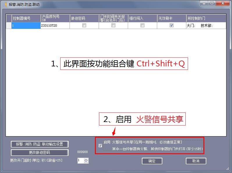
2. Connect the expansion board to the network as shown in the diagram.
This guide ensures that users can easily understand and implement the alarm and fire linkage features for enhanced security and safety.
Overhead Line Fitting,Short Insulator Pin For Insulator Supporting,Spindle For Insulator,Ceramic Pin Insulator
Shahe Yipeng Import and Export trading Co., LTD , https://www.yppolelinehardware.com