**1. Introduction**
Pulse Width Modulation (PWM) is a technique used to control the power delivered to an electrical load by varying the width of the pulses in a signal while keeping the frequency constant. The basic principle involves adjusting the on-time (t) of a switching device within a fixed period (T). This results in an average voltage across the load, calculated as $ U = \frac{t}{T} \times V_{cc} = \alpha V_{cc} $, where $ \alpha $ represents the duty cycle and $ V_{cc} $ is the supply voltage.
PWM is widely used as an alternative to digital-to-analog converters (DACs), especially in applications like motor speed control for both DC and AC motors. It is commonly paired with H-bridge driver circuits to regulate the speed of DC motors. This method is simple to implement and offers a wide range of speed control, making it a popular choice in many electronic systems.
**2. Intel 8253 Internal Structure and Working Modes**
**2.1 Intel 8253 Internal Structure**
The Intel 8253 is a programmable timer/counter chip used in microcomputer systems. It consists of three independent 16-bit decrementing counters, each capable of operating in either binary or BCD mode based on software configuration. Each counter supports six different operational modes, which are also set via software.
Each counter has three main inputs: a clock input (CLK), a gate input (GATE), and an output (OUT). The data and command access to the Intel 8253 is controlled through address lines A0 and A1, along with read (RD), write (WR), and chip select (CS) signals. The pin layout of the Intel 8253 is illustrated in Figure 1, labeled as U3.
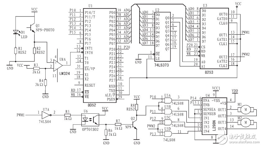
Figure 1: PWM speed control circuit using Intel 8253 and L298N
**2.2 Working Modes Related to PWM** Among the various modes available, Mode 1 and Mode 2 are most relevant for generating PWM signals. **(1) Mode 1 – Software Triggered One-Shot** In Mode 1, the microprocessor can send a 16-bit value M to the counter using two output commands. During this time, the output remains inactive. However, once a rising edge is detected at the GATE input, the counter immediately starts counting down from M, and the output generates a negative pulse with a width of $ M\tau $. This mode is ideal for generating single pulses with adjustable durations. **(2) Mode 2 – Rate Generator** When a counter is set to Mode 2, the microprocessor sends a 16-bit value N to the counter. After the command execution, the counter begins producing a continuous square wave with a period of $ N\tau $. This mode is useful for generating periodic signals with fixed frequencies. By configuring Counter 0 in Mode 2 and Counter 1 in Mode 1, and connecting them as shown in Figure 4, a simple PWM generator can be created. Before starting, the value N is loaded into Counter 0, and the value M (where $ M < N $) is loaded into Counter 1. Counter 0 then outputs a continuous square wave with a period of $ N\tau $. Every $ N\tau $ time, the GATE input of Counter 1 receives a positive transition, triggering a negative pulse of width $ M\tau $. By changing the values of M and N, the duty cycle of the PWM signal can be easily adjusted.Wire Harness Sleeve,Wire Harness Protection Sleeve,Automotive Wiring Harness Sleeve,Wiring Harness Braided Sleeve
Dongguan Zhonghe Electronics Co., Ltd. , https://www.zhonghesleeving.com