A phone ringing sounded, come to the office to meet, hardware engineers, software engineers, sales called by the boss to the office meeting. The sales staff excited and shouted: The boss, the products sent out have appeared many instability, the customer demanded immediately to the scene to solve, otherwise the consequence is serious! The engineers shivered, worried about problems every day, and who knew there were blind people. Many engineers encountered this scenario. After troubleshooting, it was found that most of them were due to power instability. Problems are difficult to prevent, how to easily get the design, to avoid product installation problems? The ZLG Technology R&D Center has summarized over 10 years of customers and its own "difficulty", carefully prepared 12 technical articles on embedded hardware power supply design, and discussed with readers the considerations of the embedded hardware power supply design. Today, we started with an example of a product problem caused by unstable power supply to the reader.
The first example of an on-site case is that a call center project of an elevator company uses a ZLG reset monitor chip NCP803 to monitor the main control power supply. In the initial test, the system is all normal. Occasionally, a small amount of products will appear after a certain period of use. The phenomenon that the reset pin always outputs a low level causes the system to remain in a reset state, and it can only return to normal when the power is turned off and on again. ZLG FAE personally went to the scene to find that this phenomenon actually occurred, and tested the power supply voltage with a multimeter. According to this, the customer suspected the quality of the power monitoring chip, and asked us to give a test report to the original manufacturer. However, the customer's so-called "problem" products have been repeatedly tested by the ZLG engineers. The "problem chip" has passed the original test and analysis report, and the chip is completely normal. At this point, things were deadlocked and the problems were not resolved. Customers have repeatedly emphasized that their power supply design is very mature and will never have problems. ZLG conducted experiments again at the request of the customer: According to the situation described by the customer, the recovery phenomenon was used to find out the reason. Even if he did frequent power-on and power-off tests with the physical objects he sent, there was no such problem. The NCP803 is a mass-produced N chip for many years. The probability of the chip itself being a problem is negligible. However, in order to test the rigorousness, we still measured the function parameters of the chip. First of all, let's analyze the features of this series of reset chips, so that we have a certain understanding of the follow-up case analysis. As shown in Table 1.
Table 1 reset monitoring chip function
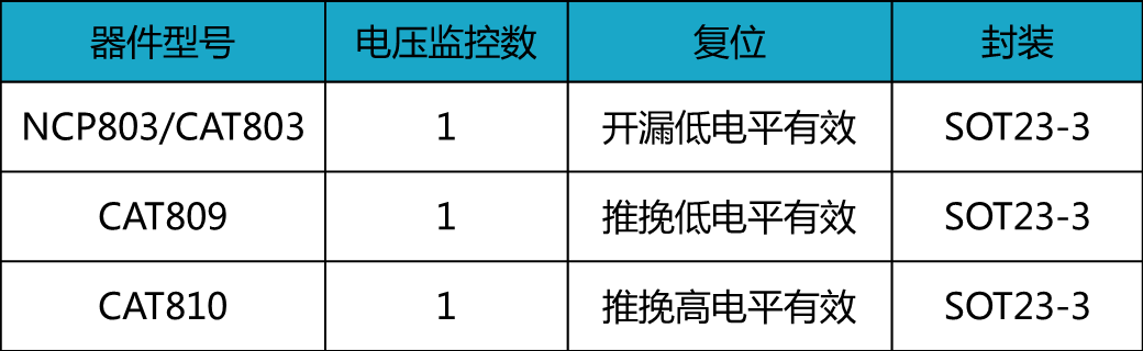
The above devices all belong to the same series, except that the reset output is not the same and does not support watchdog and manual reset. Therefore, its function is particularly simple. It only monitors the level and stability of the MCU power supply to control the reset output. Figure 1 shows the functional timing diagram of the reset monitor chip

Figure 1 NCP803 power up and down timing diagram
During the power-up process, when the VCC voltage is greater than the threshold voltage VTH+, the reset output will go high after a period of stabilization time tRP (and during this time the VCC resets the MCU operation.
When the VCC voltage is greater than the threshold voltage VTH- during power-down, the reset output will immediately pull down to the MCU to stop the program. According to the analysis of the principle of the reset monitoring chip and the actual situation of the customer can be introduced may be caused by the following problems:
Power supply VCC voltage instability or low voltage
The customer's MCU chip reset pin damage will force the reset pin down
NCP803 abnormal damage caused
In the normal test, the first step of the test should be performed to determine the problem. At this time, the voltage waveforms of the power supply VCC and the reset output need to be measured with an oscilloscope to analyze whether the voltage of the VCC is unstable or not. However, since there is no oscilloscope at the scene, a multimeter is used to simply measure the lower voltage value and the voltage value is not abnormal and it is assumed that the voltage is not problematic.
Next, we tested the power-down waveform of the reset chip on the customer's physical board. Figure 2 shows the VCC (green line) and reset (yellow line) of the reset chip when the NCP803 is actually powered on and off the customer board. Output waveform.

Figure 2 NCP803 power up and down
By analyzing the board's measured waveforms, we can see that the chip function is completely normal, and all the parameters are within the scope of the manual calibration, so we can determine that the chip is absolutely no problem. Next we suspect that there is a problem with the customer's power supply design: The ZLG FAE is strongly recommended to use the oscilloscope to test the power supply and reset waveform of the problem product to the customer's site. When FAE came to the customer's site again, there was a major discovery when using an oscilloscope, as shown in Figure 3, which is a reset waveform at the customer's site. The probe 2 shows the reset waveform. You can see the reset signal flickering. An exception occurs.

Figure 3 Reset test waveform
Since the output of the reset pin is related to the power supply, it is suspected that the VCC power supply is abnormal, and then the waveform of the power supply VCC is continued to be tested. Figure 4 shows the waveform of the power supply VCC. It can be seen that the waveform ripple of VCC is especially about 1V. Since the threshold voltage of the chip is 3.08V, the chip will reset the output when the value is smaller than this value. Therefore, it can be determined that the reason is VCC power supply. Instability caused. This is why the reset chip's reset pin will flicker.

Figure 4 Power Supply Waveform Test
This phenomenon is not happening after using a stable power supply. The final reason is that the voltage ripple output from the 12V to 3.3V DC-DC switching power supply of the customer's front end is particularly large, and it is recommended that the customer modify the inductance value. Ripple interference has been significantly improved, customers are more satisfied with the test results, and admit that it is not a problem to reset the monitor chip.
to sum up:
For this type of reset monitor chip, most of the exceptions are caused by problems with the user's power supply voltage. The probability of damage to the chip itself is negligible. When this type of phenomenon is encountered, only the oscilloscope can be used to test the voltage waveforms everywhere. Can easily find the problem, must not simply use a multimeter to simply test the voltage value, because the multimeter's refresh rate is slow, can not test the actual voltage waveform value, can only measure the average value, can not explain the situation. This case also shows the importance of power supply parameter design. Especially for DC/DC, the advantage is high conversion efficiency. The disadvantage is that the ripple is large, and it is necessary to select the appropriate inductance parameter to suppress the ripple.
Shenzhen Ousida Technology Co., Ltd , https://www.osdvape.com