TI's PGA400-Q1 is an interface device for pressure sensors, stress gauges and capacitance sensing components, integrating an analog front end (AFE) directly connected to the sensing element, as well as a voltage regulator and oscillator, including Sigma-Delta ADC, 8051 WARP core microprocessor and 8KB OTP memory, 89B EEPROM and 256B data SRAM. Mainly used in pressure sensor signal conditioning, horizontal sensor signal conditioning and humidity sensor signal conditioning. This article introduces the main features of PGA400-Q1, functional block diagram and Automotive ±500A Precision Current Sense Reference Design TIDA-03040 main features, block diagrams and system specifications, block diagrams and circuit diagrams, bill of materials.
The device incorporates the analog frontend (AFE) that directly connects to the sense element and has voltage regulators and an oscillator. The device also includes a sigma-delta. The PGA400-Q1 device is an interface device for piezoresisTIve, strain gauge, and capaciTIve-senseelements. Analog-to-digitalconverter (ADC), 8051 WARP core microprocessor, and OTP memory. Sensor compensation algorithmscan be implemented in software. The PGA400-Q1device also includes two digital-to-analog converter (DAC) outputs.
PGA400-Q1 main features:
1• Analog Features
– Analog Front-End for Resistive Bridge Sensors
– Self-Oscillating Demodulator for CapacitiveSensors
– On-Chip Temperature Sensor
– Programmable Gain
– 16-Bit, 1-MHz Sigma-Delta Analog-to-DigitalConverter for Signal Channel
– 10-Bit Sigma-Delta Analog-to-Digital Converter for Temperature Channel
– Two 12-Bit Digital-to-Analog Outputs
• Digital Features
– Microcontroller Core
– 10-MHz 8051 WARP Core
– 2 Clocks Per Instruction Cycle
– On-Chip Oscillator
– Memory
– 8KB of OTP Memory
– 89 Bytes of EEPROM
– 256 Bytes Data SRAM
• Peripheral Features
– Serial Peripheral Interface (SPI)
– Inter-Integrated Circuit (I2C)
– One-Wire Interface (OWI)
– Two Input Capture Ports
– Two Output Compare Ports
– Software Watchdog Timer
– Oscillator Watchdog
– Power Management Control
– Analog Low-Voltage Detect
• General Features
– AEC-Q100 Qualified With the FollowingResults:
– Device Temperature Grade 1: –40°C to+125°C Ambient Operating Temperature
– Device HBM ESD Classification Level 2
– Device HBM ESD Classification Level C3B
– Power Supply: 4.5-V to 5.5-V Operational, –5.5-V to 16-V Absolute Maximum
PGA400-Q1 application:
Pressure Sensor-Signal Conditioning
Level Sensor-Signal Conditioning
Humidity Sensor-Signal Conditioning
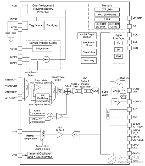
Figure 1. Functional Block Diagram of PGA400-Q1
Automotive ±500A Precision Current Detection Reference Design TIDA-03040
This shunt-based current sensor reference design provides an accuracy of < 0.2% FSR over a temperature range of -40°C to +125°C. Precision current sensing is essential in a number of automotive applications, including battery management systems, motor currents , and others. Generally, nonlinearity, temperature drift, shunt tolerances in these locations can cause poor accuracy results. This design solves these problems by using TI's current shunt monitors and signal conditioners (INA240, PGA400-Q1).
Vehicles are becoming more electrified—not just electric vehicles or hybrid-electric vehicles, but evengasoline and diesel powered machines. It becomes more critical to accurately monitor the current consumption to ensure performance as well as long-term reliability. As motor control, DC/DC, battery monitoring, and so on. The performance of any current sensor solution mainly depends on the device specifications such as accuracy, bandwidth, linearity, precision, or efficiency. Designing a system that satisfies all the required specification is a challenging task. This TI Design shows how to handle some of these parameters: accuracy, linearity, and precision.
Current can be measured in many ways such as Faraday's induction law, Ohm's law, Lorentz force law, magneto-resistance effect, and the magnetic saturation. This reference design is based on Ohm's law based shunt current sensing. Each technology has its own advantages and disadvantages , depending on the place of use every customer has his or her own preference of which topology to choose. When designing the current sensor, it is essential to choose where exactly current is being measured, its currentmeasurement range, its low side or high side, and whether It is uni- or bidirectional; the topology and design can be defined based on these parameters. As it becomes a new trend, 48 V implies the current sensor requires a larger span on current measurement range. By considering these prameters, the present reference design topology is defined As follows:
• Measurement range: ±500 A, implies bidirectional
• Low side or high side (configurable)
• Accuracy: 0.2% FSR
• Temperature range: –40°C to 125°C
To elaborate these specifications: a ±500-A current is made to pass through the 100-μΩ shunt. Across theshunt there is a noticeable amount of voltage drops. Using TI's current shunt monitor (INA240 (1)), thissmall amount of voltage drop Is measured and given to the PGA400-Q1 for linearity and compensationalgorithms to create a ratio-metric voltage in between 0.5 to 4.5 V.
Automotive ±500A Precision Current Detection Reference Design TIDA-03040 Main Features:
Accuracy of 0.2% FSR, over temperature (-40°C to 125°C)
Suitable for ±500A, high/low-side current sensing
Compensated for temperature and non-linearity (second order temperature and linearity compensation algorithm)
Protection against harness faults (overvoltage, reverse polarity, input/output signal protection)
Electromagnetic interference (EMI) protection
Reference Design TIDA-03040 Application:
• 48-V or 12-V Battery Management Systems
• Motor Control Systems
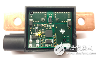
Figure 2. Automotive ±500A Precision Current Sense Reference Design TIDA-03040 Outline Drawing
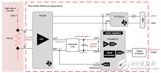
Figure 3. Reference Design TIDA-03040 Functional Block Diagram
Reference design TIDA-03040 system indicators:
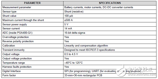
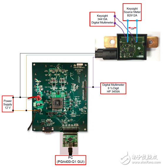
Figure 4. Calibration connection diagram for reference design TIDA-03040 and PGA400-Q1 EVM
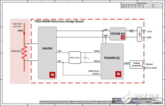
Figure 5. Reference Design TIDA-03040 Circuit Diagram (1)
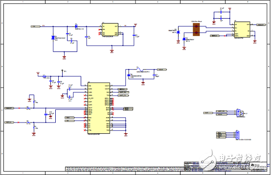
Figure 6. Reference Design TIDA-03040 Circuit Diagram (2)
Figure 7. Reference Design TIDA-03040 Circuit Diagram (3)
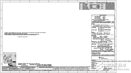
Figure 8. Reference Design TIDA-03040 Circuit Diagram (4)
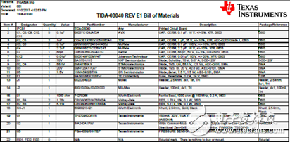
Refer to the design TIDA-03040 bill of materials:
297W Charging Medical Power Supply
297W Charging Medical Power Supply,297W Medical Device Power Supply,297W Medical Power Adapter,297W Rade Power Supplies
Shenzhen Longxc Power Supply Co., Ltd , https://www.longxcpower.com