The excitation-response test of mixed signals is becoming more and more common in today's test and measurement applications. Usually such applications require a specific analog or digital signal to be input as an excitation signal to the device under test, while obtaining the response signal of the device under test. The characteristics of the device under test or the judgment of the fault are characterized by analyzing the response signal or comparing it with the desired signal. Because today's electronic products are increasingly integrated and the types of signals involved are complex, stimulus-response testing is often a more complex test system involving mixed signals.
Let's look at two mixed-signal stimulus-response test cases, and summarize the typical requirements of the stimulus-response test application, and further extend to the necessary technologies to help readers better understand and estimate an incentive. Respond to the test system.
Test the nonlinearity of the analog-to-digital converterIn testing ADC accuracy, differential nonlinearity (DNL) and integral nonlinearity (INL) are the two most commonly used parameters to describe ADC linearity. Testing the DNL and INL parameters typically requires a simulated excitation signal to scan the entire input range of the ADC while comparing the acquired response to each desired output code width. After the comparison is completed, it is necessary to analyze the minimum and maximum values ​​or to further consider the measurement values ​​of all code widths, and draw the function curve of the entire transmission for intuitive tracking and understanding.
Such a typical stimulus-response test requires both an analog signal generator and a high-speed digital analyzer, and the synchronization between the acquisition and acquisition devices must be ensured so that the sampled points and the sample points that occur can be one by one. Correspondingly, this is crucial for accurate acquisition of DNL and INL parameters. If you are testing a high-speed ADC, you need not only a high-speed signal generation module and digital signal acquisition module, but also a high-bandwidth bus to transmit the raw data generated and acquired in real time. After collecting the data, you need a professional software platform to compare the excitation signal and response signal online, find out the data bits that are not matched, and further obtain parameters such as DNL, ​​INL, SINAD.
Ultrasound image phased arrayLet's look at a more sophisticated stimulus-response test application. Usually the frequency range of the ultrasonic signal is 20 kHz to 25 MHz or higher. The most basic method for testing the ultrasonic signal is to simulate the system by an initial pulse, then capture the reflected pulse, and describe the time delay and amplitude of the reflected pulse. The characteristics of the ultrasonic signal. The following figure describes this test method for analyzing reflected signals by excitation pulses:
Such an excitation-response test also requires an arbitrary waveform generator to generate an excitation signal for portions of the device under test, while capturing a reflected pulse of the response with a high speed digitizer. Accurate synchronization between the waveform generator and the digitizer is particularly important because of the need to measure the time delay of the reflected signal. Ultrasound image phased arrays can greatly reduce the time of nondestructive ultrasound testing by rigorously synchronizing the individual pulses that occur and the eight channels of the digitizer.
Essential technology for incentive-response testingBy summarizing the above two practical applications, it is not difficult to generalize the typical requirements of the stimulus-response test as follows:
1. Requires testing of mixed signals: analog, digital, and even RF signals
2. In order to get raw data for subsequent analysis, high-speed data bus bandwidth is required.
3. In order to ensure measurement accuracy, precise synchronization between the excitation and response signals is required.
4. Software platform support, providing professional and easy-to-use analysis tools
Figure 1. System block diagram of the ADC characterization test.
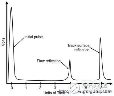
Figure 2: Characterization by pulse in an ultrasonic test.
In response to these needs, a modular architecture that is software-centric and integrates high-speed data buses and precise timing synchronization is the best platform for solving such applications. It is recommended to use the modular architecture of PXI (PCI eXtensions for test instruments) platform, which integrates various industry standard technologies (such as PCI/PCI Express bus, standard OS technology, etc.) and adds industrial grade Rugged design and integrated timing and synchronization make PXI the ideal modular industrial platform for today's test and measurement applications.
Today, there are more than 1,500 PXI-compliant modular test instruments from more than 70 manufacturers, including digitizers, arbitrary waveform generators, high-speed digital I/O, digital multimeters, RF equipment, etc. The satisfaction of the stimulus-response test for the need for mixed signals. The test modules of these mixed signals are connected through the PXI backplane bus, and the collected raw data is transmitted to the controller through the high-speed backplane bandwidth (132MB/s) for subsequent processing and analysis. When it comes to higher frequency (such as IF and RF) signals, the PCI Express-based PXI Express bus can provide up to 6GB/s backplane bandwidth for most high-speed excitation-response measurement applications.
Air conditioning heating: After turning on the heating function, the high-temperature coolant in the engine will flow through the heating water tank. At this time, the air blown by the blower will also pass through the heating water tank, so that the air outlet of the air conditioner can blow warm air. Refrigeration of car air conditioner: After pressing the ac button, the compressor clutch of the car air conditioner will be engaged. At this time, the engine will drive the compressor to operate. The compressor can continuously compress the refrigerant and deliver the refrigerant to the evaporating box. The refrigerant is evaporating The inside of the box will expand and absorb heat so that the refrigerant can cool the evaporating box.
Cross-Flow Fan,Cross Flow Blower,Cross Flow Blower Fan,Cross Flow Cooling Fan
Original Electronics Technology (Suzhou) Co., Ltd. , https://www.original-te.com