**1. Supercapacitor Voltage Equalization Model**
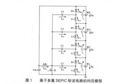
The supercapacitor voltage equalization model used in this study is based on a multiple SEPC (Single-Ended Primary Inductor Converter) chopper circuit, where four supercapacitors—B1 to B4—are connected in series. As shown in Figure 1, the circuit consists of capacitors Ca, inductors L, switches Q, and diodes D (F1 to F4). The capacitor C serves as the main power source for the entire circuit, eliminating the need for an external power supply. This design simplifies the circuit topology by using only one switching device, Q. Additionally, since the switch Q is grounded, there is no need for a floating gate driver IC, making the driving circuit more straightforward. During the equalization process, the switching duty cycle remains constant, and there is no requirement to detect the individual cell voltages of the series-connected supercapacitors. When operating in Discontinuous Conduction Mode (DCM), the system does not require feedback control, reducing overall control complexity.
**2. Analysis of the Equalization Principle of the Multiple SEPC Chopper Circuit**
**2.1 Equalization Principle**
The equalization principle of the multiple SEPC chopper circuit is similar to that of the conventional SEPC chopper circuit, whether operating in Continuous Conduction Mode (CCM) or Discontinuous Conduction Mode (DCM). The voltages across the supercapacitors B1 to B4 are denoted as v1 to v4. Assuming that v2 is higher than v1, v3, and v4, the working waveforms and current directions are illustrated in Figures 2 and 3.
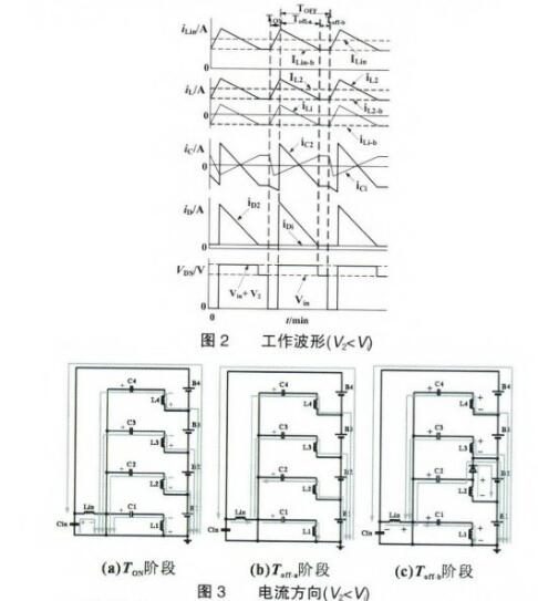
During the conduction phase of the switch Q, the currents through the inductors L1 to L4 increase, allowing them to store energy. These currents flow through the inductors and capacitors C1 to C4 toward the switch Q. When the switch Q turns off, the stored energy in the inductors is preferentially transferred to the supercapacitor with the lowest voltage, which is B2 in this case. The diode D2 becomes forward-biased, allowing the energy to be redistributed. Due to the presence of diodes D1 to D4 and the inductor, the current waveform remains stable during this process. Once the current through D2 drops to zero, the circuit enters a steady state, and the current distribution ensures that the voltages of the supercapacitors gradually reach equilibrium. At this point, the current waveforms of the inductors, capacitors, and diodes become identical.
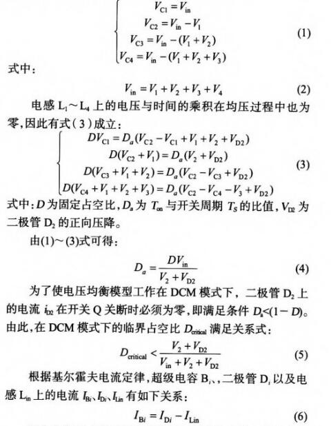
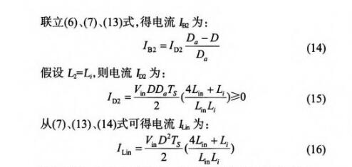
When the voltage range of V2 (the voltage across supercapacitor B2) and the input voltage v is known, the duty cycle D is set to a fixed value that satisfies equation (5). According to equation (16), if the voltage V remains constant, the inductor current L is also constant. Furthermore, from equation (4), the variation range of D is determined by the known values of V2 and v. In summary, if the duty cycle D and the voltages v and V are fixed or have a known variation range, equations (14) and (15) show that the current on diode D2 remains within a limited range. Therefore, in DCM mode, the voltage equalization model can effectively limit the current on the supercapacitor B2 to an ideal level, achieving a balanced state without the need for feedback control.
Smart Terminal,Cba Smart Terminal,Smart Payment Terminal,Pos Smart Terminal
Guangzhou Winson Information Technology Co., Ltd. , https://www.barcodescanner-2d.com