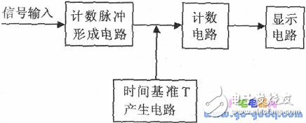
Counting Pulse Forming Circuit: This part is responsible for converting the input periodic signal into a countable pulse after amplification and shaping, making it suitable for digital processing.
Time Base T Generation Circuit: The purpose of this section is to generate a precise time interval T, also known as the gate pulse. It determines the duration during which the measured signal is counted.
Counting Circuit: This component counts the number of pulses from the signal during the time window defined by the gate pulse. The time reference circuit generates the gate pulse, allowing the measured signal to pass through and be counted only during the active period T.
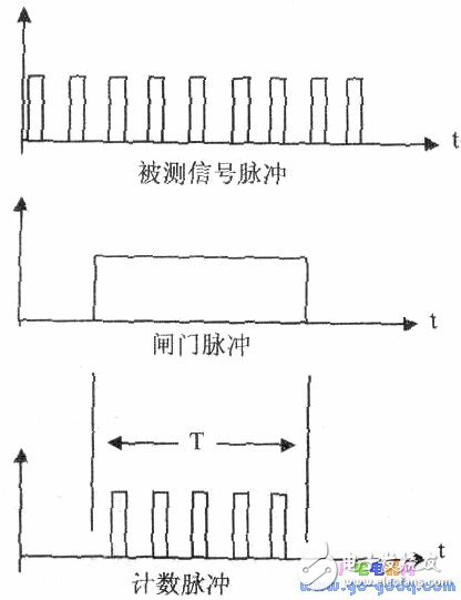
Waveform
Display Circuit: This part is used to visually present the measured frequency, typically on an LCD or LED display for easy reading.
With the increasing use of microcontrollers and their growing capabilities, the design of electronic frequency counters has evolved significantly. Modern microcontroller units (MCUs) come with built-in timer and counter modules, making them ideal for implementing both the time reference and counting functions. As a result, many traditional discrete-component circuits have been replaced by these integrated solutions. In particular, the counter function of the MCU's timer module is often the preferred choice for counting, while the timer function is used to generate the time reference T.
The MSP430 series of microcontrollers, developed by Texas Instruments, is a family of ultra-low-power 16-bit MCUs. These devices feature a RISC architecture and include numerous peripheral modules such as ADCs, timers, and watchdogs, all integrated into a single chip.
Implementing the Time Reference Circuit Using the Watchdog Timer:
The Watchdog Timer (WDT) in the MSP430 series is primarily used for system monitoring and internal timing. It operates as a 16-bit counter and offers two modes: watchdog and timer. There are eight different timing options available. In this application, the WDT is configured as a timer rather than a watchdog. Based on the specific requirements of the measurement, the WDT is set to one of the eight timing intervals, such as 1000ms, to serve as the time reference T—the duration for which the gate pulse is active.
When the MCU detects a rising edge on the input signal, it triggers the WDT timer and starts counting the incoming pulses. Once the WDT timer reaches the preset time T, it generates an interrupt. At this point, the counting stops, and the interrupt service routine handles the display of the measured frequency.
One important consideration in this approach is the accuracy of the time base T. Since the WDT is used for critical timing functions, its precision must be sufficient. Fortunately, the WDT in modern MCUs is designed to offer high accuracy, ensuring reliable operation in various applications, including system monitoring and timing control.
Car Phone Wireless Charging Coil,Circuit Board Induction Coils,Intersection Induction Coils,Induction Coil Set
Shenzhen Sichuangge Magneto-electric Co. , Ltd , https://www.scginductor.com