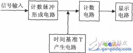
The frequency refers to the number of repetitions, cycles, or oscillations that occur in a periodic process within a specific unit of time, and it is commonly denoted as f. If a signal completes N cycles in T seconds, then its frequency can be calculated using the formula: f = N / T. The following figure shows the block diagram of an electronic counting frequency meter, which consists of four main components.
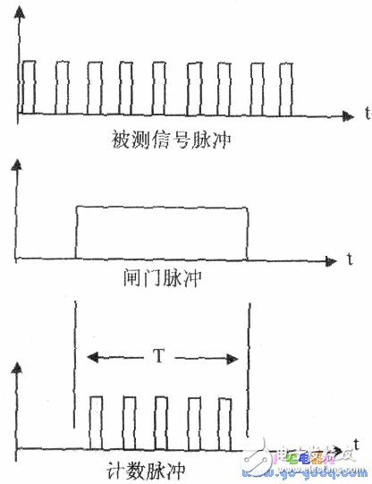
Waveform
The **display circuit** is used to visually present the measured frequency value, making it easy for users to interpret the results. With the increasing use of microcontrollers and their expanding capabilities, the design of electronic frequency meters has evolved significantly. Modern microcontrollers, such as those based on the MSP430 family, offer built-in timer/counter modules that simplify the implementation of both the time base generation and counting functions. These modules replace traditional discrete component circuits, offering greater flexibility and accuracy. The timer/counter functionality within the microcontroller is typically used as the counting circuit, while the time reference is generated using the timer module. This approach reduces complexity and improves performance. In this article, we will explore how the watchdog timer in the MSP430 series can be utilized to generate the time reference and perform the counting function. The MSP430 series is a family of ultra-low-power 16-bit microcontrollers developed by Texas Instruments. They are designed with a RISC architecture and include various integrated peripherals such as ADCs, timers, and watchdogs. **Using the Watchdog Timer for Time Base Generation** The Watchdog Timer (WDT) in the MSP430 series is primarily used for system monitoring and internal timing. It is a 16-bit counter that operates in two modes: watchdog and timer. There are eight different timing options available. In this application, the WDT is configured as a timer to generate the time reference T. For example, it can be set to a specific interval like 1000 milliseconds. When the microcontroller detects a rising edge on the input signal, it starts the timer and begins counting the incoming pulses. Once the timer reaches the predefined interval (T), the watchdog interrupt is triggered. At this point, the counting stops, and the interrupt service routine processes the result. The frequency value is then displayed using a display subroutine. An important consideration in this design is the accuracy of the time base T. Since the watchdog timer is used for critical timing functions, it must maintain high precision. Otherwise, it would not be reliable for system monitoring or timing applications. Fortunately, the internal clock sources of modern microcontrollers provide sufficient accuracy for most frequency measurement tasks.Induction Coils,Electronic Eye Induction Coils,Rectangular Induction Coils,Induction Coils For Medical Industry
Shenzhen Sichuangge Magneto-electric Co. , Ltd , https://www.scginductor.com