Research on Serial Communication in Parallel Control System Based on Dual DSP
Abstract: A brief introduction to the basic performance of TMS320F2812 DSP, focusing on the use of DSP SPI module for dual DSP synchronous serial communication, and under Visual Basic 6.0, using MSComm control to achieve asynchronous serial between the upper PC and the lower DSP The specific implementation of communication. Finally, an example of information transmission using RS-232 serial communication standard is given. The serial communication is simple, the interface is friendly, and the application field is wide.
introduction
With the widespread use of digital signal processors (DSPs) in the field of system control, the communication problems between DSPs that control various systems have become increasingly prominent. Using the high-speed synchronous serial interface (SPI) module of the DSP itself, the DSP can be directly docked to realize synchronous serial communication between chips. Sometimes, in order to make full use of PC resources, some problems that are difficult to solve on smart instruments, such as curve display, can be realized on PCs. This requires a serial communication interface (SCI) module embedded in DSP to realize DSP and host computer. Asynchronous serial communication.
The background of the communication method introduced in this paper is to build a double-switched reluctance servo motor parallel drive system (SRSD) for the research team. The system uses the TMS320F2812 chip, with SPI module and SCI module [1]. This article introduces in detail the hardware connection and software implementation method of serial communication between SPI module and SCI module, so as to complete the implementation of dual SRSD system communication module based on TMS320F2812.
1 System Introduction
The dual motor parallel system has many advantages. It is more flexible than the single motor system in handling the space placement of the motor, and it is conducive to improving the characteristics of the motor. Compared with the single motor system, under the same output condition, the total rotational inertia of the dual motor is smaller, which can reduce the power consumption during operation. In addition, when one of the two motors is damaged, the other one can still continue to operate in a short time or under the condition of appropriately reducing the load, which improves the reliability of the system [3].
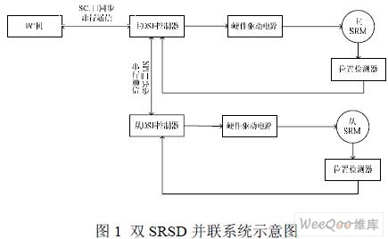
The background of this paper takes SRSD as the main research object, and position output as the main control quantity. Based on the stand-alone system, after improvement, a dual SRSD parallel system is designed. The system block diagram is shown in Figure 1.
2 Principles and characteristics of serial communication
In a computer, an 8-bit binary code is usually used to represent a character, and the binary code of each character of a message is sent from low to high bit sequentially, and the communication method is called serial communication. It is characterized by being sent bit by bit. According to the transmission direction of information, serial communication can be divided into simplex communication, half-duplex communication and full-duplex communication. What is adopted in this article is a full-duplex communication method. Serial communication can be divided into synchronous mode and asynchronous mode according to different transmission methods. The synchronous mode is more complicated, but the transfer rate is higher than the asynchronous mode. In this article, SPI adopts synchronous mode and SCI adopts asynchronous mode.
The SPI of TMS320F2812 is a high-speed synchronous serial input / output port, which is generally used to realize communication between DSP controllers and between DSP and peripheral devices. SPI has two operation modes: master operation mode and slave operation mode. The main chip controls the clock signal (SPICLK), which can initiate data transmission by sending the SPICLK signal at any time. Regardless of whether it is a master chip or a slave chip, data is shifted out of the shift register on one edge of SPICLK, latched in the shift register on the opposite edge of SPICLK, and both output and receive data are performed simultaneously.
The SCI of the chip is an asynchronous serial communication interface for two-wire communication, also called UART port, which is generally used to connect to the host computer (hereinafter referred to as PC).
3 Design of synchronous communication module
3.1 Hardware design based on SPI module
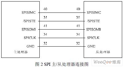
Let the two DSPs work in the master and slave operation modes respectively. The pin connections of the two are shown in Figure 2. The main processor provides the serial clock to the entire communication network through the SPICLK pin to control the data transmission of the system; provides the chip select signal to the slave processor through the SPISTE pin, and the low level is effective; the data is output to the slave processor through the SPISMO pin On the SPISIMO pin; the data on the SPISOMI pin of the slave processor is accepted through the SPISOMI pin.
3.2 Synchronous communication process design and software implementation
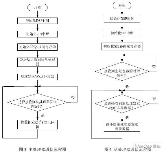
In design, the master processor first sends the given information to the slave processor. After the transmission is completed, it sends 0 cyclically, so that SPICLK has a continuous clock pulse output, and waits to accept the data sent from the processor. The slave processor first waits for the given information. If it receives non-zero data, it performs the next step and continuously sends the current data to the master processor.
The flow chart of the SPI communication master processor and the slave processor are shown in Figure 3 and Figure 4, respectively.
After completing the initialization of the two DSP clocks and interrupts, set their SPI registers separately and put them in master and slave modes respectively. Both the master and slave processors use query to send data, and interrupt to receive data.
Query transmission is to determine whether the SPI transmit buffer full flag bit (SPISTS.bit.BUFFULL_FLAG) is empty. If it is empty, write the data into the transmit buffer register (SPITXBUF) to start the data transmission of the SPISIMO pin. After transmission, SPISTS.bit.BUFFULL_FLAG is automatically cleared, waiting for the next transmission.
The interrupt mode is accepted when the SPI interrupt enable bit (SPICTL.bit.SPIINTENA) is set. If the received data is transferred to the SPI serial data register (SPIDAT), the SPI interrupt flag bit (SPISTS.bit.INT_FLAG) Set and trigger an interrupt, and transfer the data to the acceptance buffer register (SPIRXBUF). If the data in SPIRXBUF is read, SPISTS.bit.INT_FLAG is automatically cleared and waits for the next acceptance interrupt.
The SPI part sending and receiving procedures are as follows:
void spi_TxProcess ()
{
while (SpiRegs.SPISTS.bit.BUFFULL_FLAG == 1) {}
/ * Determine whether SPISTS.bit.BUFFULL_FLAG) is empty * /
if (SpiRegs.SPISTS.bit.BUFFULL_FLAG == 0)
{
SpiRegs.SPITXBUF = slave_value;
/ * Write data to SPITXBUF to start data transmission * /
}
}
interrupt void SPIRXINTA_ISR (void)
/ * Accept interrupt mode * /
{
TX_data2 = SpiRegs.SPIRXBUF;
/ * Automatically clear interrupt flag after reading SpiRegs.SPIRXBUF * /
return;
}
4 Design of asynchronous communication module
4.1 SCI-based hardware design
Figure 5 shows the hardware connection diagram of the host computer and DSP. RS-232C standard uses negative logic: logic "1" is a low level between -5V ~ -15V, usually expressed by -12V; logic "0" is a high level between + 5V ~ + 15V, usually used + 12V means. The above standard is called EIA level.
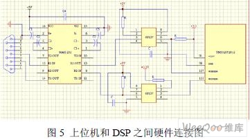
RS-232C uses positive and negative voltages to represent the logic state, and it is negative logic, while TTL uses high and low TTL device levels to represent the logic state and is positive logic. The provisions of the two are different. In order to be able to connect with the EIA device and ensure the normal communication between the two, the level and logic relationship must be changed between them. The integrated chip MAX232 produced by the Maxim company implements this transformation [4]. The changed level is converted to a signal within + 3.3V suitable for TMS320F2812 after 6N137.
4.2 Software implementation of SCI communication
Before communication, the sender and receiver must use the communication protocol agreed by both parties, and the data is split into bits for transmission. The order of transmission is start bit, data bit, parity bit, and stop bit. The number of bits transmitted per second is determined by the baud rate. The communication protocol in this article is set to: baud rate 38400bit / s, 8 data bits, no parity, 1 stop bit, data transmission using both ASC â…¡ code and binary form.
The upper computer adopts Visual Basic 6.0 (hereinafter referred to as VB) language programming to achieve, using the MSComm control provided in VB can realize the communication between the PC and the lower computer. There are two ways to communicate using MSComm: One is the event-driven method, which is the OnComm event. When data arrives at the port or the port state changes or a communication error occurs, the OnComm event will occur. The other is the query method. The query method is to find out whether there is an event and process it by periodically reading the signal of the buffer. In this design, the query is sent and the event-driven method is accepted. The initialization procedure of the MSComm control is as follows:
MSComm1.CommPort = 1 'Port number'
MSComm1.SetTIngs = "38400, n, 8,1"
'Baud rate 38400bit / s, 8 data bits, no parity, 1 stop bit'
MSComm1.InputLen = 0
MSComm1.InBufferCount = 0 'Clear receive buffer'
MSComm1.OutBufferCount = 0 'Empty'
MSComm1.RThreshold = 1 'Number of characters that can be received in the receive buffer or send buffer'
MSComm1.PortOpen = True
According to actual requirements, we have to simultaneously transmit data and control characters in communication, so data transmission adopts both ASCâ…¡ code and binary form. This requires changing the properties of MSComm1.InputMode before each transmission.
After completing the clock and interrupt initialization, TMS320F2812 (main processor in SPI communication) sets up its SCI register to make its communication protocol consistent with the host computer. TMS320F2812 uses query to send data to the host computer, and interrupt mode to accept data from the host computer. The SCI register settings are as follows:
SciaRegs.SCICCR.all = 0x0007;
/ * One stop bit, disable parity check, prohibit self-test, 8 characters * /
SciaRegs.SCICTL1.all = 0x0003;
/ * Prohibit accepting error interrupts, reset, prohibit dormancy, turn on transmission enable * /
SciaRegs.SCICTL2.all = 0x0002;
/ * Open to accept interrupt, close to send interrupt * /
SciaRegs.SCIHBAUD = 0x00;
SciaRegs.SCILBAUD = 0x79;
/ * Baud rate 38400 * /
SciaRegs.SCICTL1.all = 0x0023;
/ * Start to enable SCIA * /
5 Conclusion
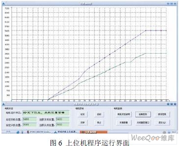
The above is the software and hardware design solution to solve the communication between the two DSPs and between the DSP and the PC. When the upper computer sends the given information (position information), the lower computer receives the data and transmits it to the SPI processor. The upper computer The interface with the lower computer is shown in Figure 6 and Figure 7.

The biggest feature of the system is that it uses simultaneous synchronous and asynchronous communication methods according to actual needs. The synchronous serial communication between the two systems ensures the synchronization of the two systems; through the asynchronous serial communication between the PC and the host computer, a series of data collected by the DSP is sent to the PC through the serial port, which solves the DSP storage space For limited problems, you can easily process some data on the PC that is difficult to achieve on the DSP, get some data curves, etc. The effect is intuitive and convenient. This system has been applied in a parallel control system of a switched reluctance motor, with stable operation and good communication performance.
1. An open structure of heating elements with half round stainless steel
reflectors for an optimal use of energy.
2. The Gyros will change direction automatice, if there is a force.
3. Removable and detachable parts for easy clean.
4. The particular broiling result is obtained by alternating heating and
cooling down. The meat fibres do not harden, and the gravy is flavoured
by the spices. This cooking mode results in very healthy meat.
5. The Vertical Grill allows broiling meat layers, shashlik, party sausages,
poultry and fish with few attachments.
6. The Skewers and Gyros go in opposite direction so that the food could
be heated more well.
7. Power: 1400W

Horizontal Design Bbq Grill ,Grill Big Chicken,Grill Pork Tenderloin Bbq,Grill And Bar Close To Me
Housoen Electric Manufacture Co., Ltd. , https://www.housoenappliances.com