0 Preface
The multipoint control unit (MCU) of the video conference is the core equipment of the video conference system. All terminals participating in the conference can establish a one-to-one connection with the MCU. The terminal is responsible for collecting the sound and images of the conference site, and then encodes and transmits them to the MCU. The MCU determines the processing method of audio and video signals according to the current video conference mode and Forwarding logic, and finally send the processed audio and video data to each participant.
1 Classification of multipoint video conferences
Based on the H.324 standard, there are various methods and configurations for the realization of multipoint conferences, which can mainly be centralized multipoint conferences and decentralized multipoint conferences.
A centralized multipoint conference is organized by a multipoint control unit. All terminals send video streams, audio streams, and control streams to the multipoint control unit in a point-to-point manner. Its structure is shown in Figure 1. The multipoint controller in Figure 1 uses the H.245 control function to centrally manage the conference. H.245 can also be used to specify the communication capabilities of each terminal. The multi-point processor can perform mixing, data distribution, and mixing and switching of video signals, and send the processing results back to the terminal participating in the conference. A typical multipoint control unit that supports centralized multipoint conferences usually consists of a multipoint processor and a multipoint controller.

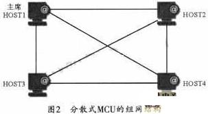
Decentralized multipoint conferences are not available in traditional conference systems (such as H.320). There is no MCU in the system of this management mode, and there is no device for centralized control and centralized management. The functions of the MCU exist in other devices of the system in the form of MC and MP function modules. The main reason why distributed multi-point control and management can be implemented in a packet-based communication network is that the communication in the network is carried out in logical channels, not in units of physical channels. Distributed multi-point conferences are organized using multi-cast technology. The terminals participating in the conference transmit video and audio information to other participants' terminals in a multi-cast manner without the need for centralized multi-point processors. H.245 control information is still transmitted to the main multipoint controller in a point-to-point manner. Figure 2 shows the distributed MCU network structure.
The MCU in the centralized multipoint video conference integrates the multipoint video conference controller (MC) and the multipoint video conference processor (MP). It not only has the function of organizing and managing conferences, but also is responsible for the voice and voice of all participants. Image processing and switching.
2 MCU system design
2.1 Network structure of centralized multipoint video conference
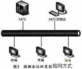
The star networking scheme is the first choice for centralized multipoint conferences. The star network solution is to connect all terminals to the MCU through a hub or a switch. Each terminal only establishes a connection with the MCU based on the H.324 standard. Figure 3 shows its star network solution. Each terminal is responsible for collecting the sound and image of the conference site, and then encoding through the corresponding encoding algorithm, and then the encoded audio and video streams are sent to the MCU through the switch, and the MCU performs audio and video separately according to the current conference mode deal with. The processing of audio and video mainly includes the mixing of participants' voices and multi-screen synthesis. Finally, the processed audio and video data is forwarded by the MCU to each participant's terminal according to the conference mode.
The setting of the video conference mode and the management of the members participating in the conference can be completed by the MCU console. In practical applications, a conference manager, also known as a conference manager, is usually provided for each conference. The conference administrator can remotely control the multipoint control unit through the MCU console, including setting the start and end time of the conference, the audio and video standards adopted by the conference, the setting of the conference mode, the management of the participant list, and the loading and saving of conference templates Wait. While the conference is in progress, the conference administrator can also schedule the conference through the MCU console, including designating a new chairperson, designating a new speaker, and canceling the speech.
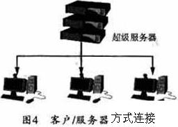
In the distributed conference scheme, each terminal completes certain control and switching functions, so it has strong flexibility. The participant's joining / exiting conference function is easy to implement, but its communication protocol is relatively complicated. Control information is sent in a broadcast manner, so the communication efficiency is relatively low, so a centralized implementation scheme is usually adopted. Sometimes, the chairman can also merge with the MCU to form a super server. This approach can evolve into a client / server system that people are familiar with. This method has very outstanding advantages when the mobility requirements of the chairman's end are not high, such as easy implementation and easy control. Figure 4 shows the structure of the client / server MCU. In order to ensure versatility and mobility, this design uses a centralized MCU solution.
2.2 MCU communication interface design
The main functions of the communication interface are data serial / parallel conversion and buffering, and its function is similar to the serial port expansion of a larger input and output buffer. The serial data format input from the modem (Modem) is 2-8-1-N, that is, 2 bit start bit, 8 bit data, 1 bit stop bit, no parity. The interface card separates the 8 bit data bits and performs serial / parallel conversion to store them in the input buffer. The buffer is an 8 kbit FIFO (first in first out) stack. The interface card provides the specified address so that the microcomputer can read data from it. The data output by the microcomputer can be written into the output buffer of the interface card. It is also an 8 kbit FIFO stack, and then the interface card performs the opposite operation and outputs it to Modem [17]. The principle of the interface card is shown in Figure 5.

2.3 Simplified model of video conference system protocol
The design of MCU can refer to ITU's H.324 series of recommendations. This proposal draws up the basic framework of low-bit multimedia communication terminals. It includes four main parts: G.723.1 audio coding standard, H.263 video coding standard, H.245 communication control protocol, and H.223 multiplex tapping protocol. The proposal also describes the adoption of V. in PSTN. 34 Standard Modem. The V.34 standard specifies the data format, bit rate and other requirements of the input / output Modem. In this system, because the MCU is connected to multiple ports, if the modem rates of each port are inconsistent, it may cause data congestion in the MCU. Therefore, automatic adjustment of the modem rate is prohibited in this system. Generally, before the conference starts, the connection is established at the lowest rate of each port to ensure a small bit error rate. In the MCU, the header of the H.223 frame is mainly processed. The frame start flag in the H.223 frame structure is 3 consecutive FAS codes, each FAS code is 4 bytes long, which can be taken as 0XEC in the test system. This flag can also be used to delimit H.223 frames. Since the frame length is indefinite, the correct transmission and detection of the frame start flag directly affect the frame positioning. The control signal also occupies 4 bytes, of which the first two bytes are BAS codes and mainly carry conference control information. Because the conference system has fewer possible states and fewer control commands are used, only one byte is used to transmit the command, and the other byte is used as the error correction byte of the BAS code to ensure the correct transmission of the command.
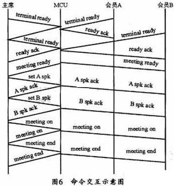
In the command interaction of the video conference system, the MCU and each participating site must maintain a status setting table during the conference. The table records the logical ports, telephone numbers, geographic locations, and identities of the conference sites. (Chairman, speaker and ordinary member), etc. After that, the MCU further maps the logical port to the corresponding physical address so that the MCU can read and write information from the address. The initial setting of the status setting table is determined by the service call before the meeting. The scheduled meeting time is the responsibility of the MCU to call the participating sites through the Modem to establish a data link. When a certain station calls, the station inserts the terminal ready command in its H.223 frame, and the MCU loops back the frame and replaces the BAS code with the ready confirmation command. When all sites are ready, the MCU sends a conference ready command to each site. At the same time, the data of the chairman terminal is switched to each site, at this time, the chairman can speak, and can also order other members to speak. If the chairman does not send a command to the MCU, the conference in progress status indication is sent to the MCU, and the MCU maintains the current state; if the chairman commands the site A to speak, it inserts a command to make A speak in the H.223 frame. After receiving the command, the MCU switches the data of site A to all sites except A, and sends the data of the chairman to site A at the same time. When the chairman commands the end of the conference, the MCU sends a conference end confirmation command to each site and stops working. Each site hangs up the modem. 6 is a schematic diagram of command interaction in the above process.
During the meeting, after the MCU receives the chairman's command, it should modify the state setting table according to the state transition generated by the command. Through the low-speed MCU servo software, the MCU can simultaneously control the data reading and writing operations of the eight participating sites, and simultaneously perform command interpretation and execution. Since the frame exchange takes up a lot of memory resources and at the same time guarantees the real-time performance of the system, the design of the MCU servo software requires not only high execution efficiency, but also requires that the program itself take up less system resources.
3 MCU software design
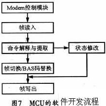
The design of the software can be completed using rapid prototyping methods. First, a simplified rapid prototype can be established, and then gradually improved on this basis to meet the design requirements. Rapid prototyping can also use a modular method to divide the entire MCU software into several loosely coupled functional modules, and design and test each module separately. After ensuring that each module is correct, comprehensive debugging of the entire software can be performed to discover each There may be mistakes in the interface design between modules, and in turn, the entire software design is completed by modifying the program of each module. The specific development process is shown in Figure 7. The work of each step is now described as follows:
(1) When using a telephone line to communicate data between two computers via Modem, it can be used as a rapid prototype with the simplest function. The main work of this step is to establish the control function of Modem on DOS platform. The key is to interpret the typed command and send it to the Modem, and at the same time receive the Modem's feedback signal to determine the Modem's status and use it for further control;
(2) Establish a remote self-loop model to test the accuracy of rapid prototyping and test the working characteristics of the interface card;
(3) Write frame reading module and frame writing module program to continuously test frame loopback and single test frame. Verify the correctness of the transmitted test frame reading block and frame writing module;
(4) Write the command extraction and interpretation module and the state modification module program, and verify the correctness of the above modules by changing the BAS code of the test frame and reading the state modification result;
(5) Write a frame switching / BAS code replacement module program, construct a test platform among three computers, and make one of them act as an MCU, and then verify the correctness of the above modules by the test frame switching at the other ends;
(6) According to the actual conditions, establish a test platform between multiple computers, and appropriately change the length of the test frame (128 ~ 512 byte), continuous testing and timing to verify the working delay of each module. Then, according to the real-time requirements of the system, the modules with large delay are improved.
4 Conclusion
Since MCUs have different processing capabilities for video images with different degrees of motion, when transmitting video images with different degrees of motion, when the video quality received by terminal B is good, the maximum number of MCU access terminals (MCU ’s Capacity) is different. The test found that the MCU designed in this paper has good audio and video images when the amount of motion is relatively large (when n = 16); when n = 20, the audio and video effects are basically acceptable, but the image is occasionally distorted; and when n = 32 , The color of the image is severely distorted, and the sound is intermittent. At the same time, the specified values ​​of video conferences such as image delay and delay jitter (synchronization of voice and image) are considered (point-to-point image delay does not exceed 150 ms, and delay jitter is about 400 ms). It can be concluded that the unit capacity of this MCU should be 16 when the image quality is good and the image delay and delay jitter can meet the specified requirements.
Chengdu Zysen Technology Co., Ltd. , https://www.zysenmw.com