introduction
Shortwave communication is the use of ground waves or low ionosphere for medium and short distance communication of tens of kilometers to hundreds of kilometers, and ionospheric reflection for long distance communication of thousands or even tens of thousands of kilometers. Affected by the complex time-varying factors such as Rayleigh fading, multipath effect, and Doppler frequency shift in the ionosphere, short-wave communications equipment is expensive to test and install. In order to test the performance of various shortwave wireless communication systems, there are usually two methods, one is experimental testing and the other is channel simulation. In the experimental test, in order to test the performance of short-wave communication equipment, it is often necessary to carry out a large number of long-distance off-site experiments and long-term tests in the actual communication environment, which is very difficult to achieve; Conduct theoretical analysis, establish a channel model, and perform simulations similar to actual channels in a laboratory environment. It can easily produce a variety of typical channel characteristics and electromagnetic environments. The geographical area that can be simulated is very wide and is not limited by climatic conditions. , You can repeat the experiment many times at any time, and the test cost is low, which can shorten the development cycle of communication equipment. Among various typical short-wave channel models, the Watterson model can reflect the characteristics of the short-wave channel in most cases and has low complexity. It is recommended and widely used by CCIR.
An important issue in the study of shortwave channels is the problem of multipath propagation. Multipath propagation mainly brings two problems: fading and delay. Multipath delay refers to the difference between the maximum transmission delay and the minimum transmission delay in multipath. Multipath delay is on short-wave lines, and the most serious delay can reach milliseconds. In the study of the shortwave channel simulator, due to the relatively large delay size required, and the accuracy of the delay should be as high as possible, coupled with the real-time reasons, the amount of data is very large. For the subsequent DSP algorithm processing and the previous A / D digital and precision requirements, you can choose a large-capacity memory for large-scale delay processing, and use DSP as an interpolation algorithm for high-precision small-scale delay algorithm processing. This article focuses on the study of high-precision small-size delay algorithms, and proposes an implementation method based on interpolation technology.
1 Implementation structure of interpolation extractor
Integer multiple interpolation refers to inserting 1-1 zero values ​​between two original sampling points. The sequence and spectrum after interpolation of the original sequence x (n) are:
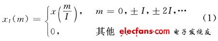
It can be seen from equation (2) that the signal spectrum after interpolation is the spectrum obtained by compressing the original sequence spectrum by I times. The spectrogram contains not only the baseband component of X (ejω), but also the high-frequency component whose frequency is greater than π / I (called it the high-frequency image of X (ejω)). In order to restore the original spectrum from XI (ejω), the interpolated signal must be low-pass filtered (filter bandwidth is π / I), and the time-domain resolution of the signal is greatly improved after interpolation. Integer multiple extraction refers to taking the original sampling sequence x (n) every D-1 data to form a new sequence xD (m), namely:

In the formula: D is the extraction multiple, which is a positive integer. The discrete Fourier transform of xD (n) is:
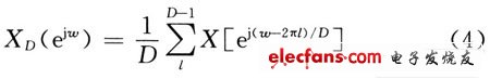
It can be seen from equation (4) that the spectrum XD (ejω) of the extracted sequence is the superimposed sum of the D spectra after the frequency shift and D-time spreading of the original sequence spectrum X (ejω) before extraction. If the sampling rate of the x (n) sequence is fs, then its unambiguous bandwidth is fs / 2. When decimating x (n) with D times decimation rate, the sampling rate of the obtained decimation sequence xD (m) is fs / D, and its unambiguous bandwidth is fs / (2D); when x (n) contains more than fs / (2D) frequency component, xD (m) will inevitably produce spectrum aliasing, resulting in the inability to recover frequency component signals in x (n) less than fs (2D) from xD (m). In order to avoid spectrum aliasing caused by extraction, a digital filter (filter bandwidth is π / D) is required to filter X (ejω) so that X (ejω) contains only frequency components less than π / D. With D-fold decimation, the decimated spectrum will not alias. It can be said that XD (ejω) can accurately represent the frequency component signal less than π / D in X (ejω), so processing XD (ejω) at this time is equivalent to processing X (ejω), but the former's data flow rate Only the 1 / D of the latter greatly reduces the requirements for post-processing speed.
The structure of the decimation and interpolation introduced earlier has a relatively high requirement on the operation speed. This is mainly manifested in the low-pass filter in the decimation filter model before the decimation operator, that is to say, the low-pass filter is at a reduced speed It was implemented before; and for the interpolator model, the low-pass filter is located after the interpolation operator, that is to say, the low-pass filter of the interpolator is performed after the speed increase. In short, no matter whether it is an decimator or an interpolator, its anti-aliasing digital filtering is performed under the condition of a high sampling rate, which greatly increases the requirements for the calculation speed and is extremely disadvantageous for real-time processing. The polyphase filtering structure of the decimator and interpolator which is beneficial to real-time processing will be discussed below.
Let the impulse response of the digital filter be h (n), and its z transformation is defined as:
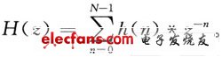
In the type, N is the filter length. If the impulse response h (n) is divided into D groups according to the following arrangement, if N is not an integer multiple of D, then h (n) is padded with zeros so that the filter length N is an integer multiple of D, that is, N / D = Q, Q is an integer, then:
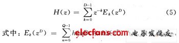
D-1. Equation (5) is the polyphase filter structure of the digital filter H (z). For the application of this article, here is an I-interpolator polyphase filter structure implementation block diagram, as shown in Figure 1. Among them, Rk (z ') = E (I-1-k) (z').
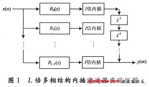
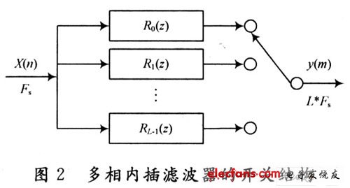
It can be seen from Figure 1 that the digital filter Rk (z) is located before the interpolator, that is, the filtering is performed before the data stream is accelerated, which greatly reduces the requirements on the processor and improves the real-time processing capability. In addition, another advantage of the polyphase filter structure is that the coefficient of each branch filter is reduced from the original N to N / I, which can reduce the cumulative error of the filter operation, help to improve the calculation accuracy, and reduce the processor Word length requirements. Fig. 2 is the switch structure form of the multiphase structure interpolation filter. It can explain more clearly how the polyphase structure interpolation filter works. For a data stream with an input rate of Fs, after passing through L sub-filters, the data stream speed of each sub-filter is still Fs, but the data stream speed of the entire interpolation filter is increased to I · Fs, at this time the rate is I · The switch of Fs selects the output data stream, that is, the acquisition of I-fold interpolation data is completed. The polyphase filter structure of D-time decimator can also be obtained.
High-Voltage Primary Switchgear
Electrical Switchgear Panel,Switchgear Power System,Gh-Voltage Primary Switchgear,Switchgear Electrical Load
Shandong Shunkai electrical equipment co., LTD. , https://www.chinasdsk.com