Introduction
At present, the research of micron and nanotechnology is very active, which has made the rapid development of microtechnology and micromechanical electronic system (MEMS) technology, which greatly promotes the miniaturization and microcosmization of medical equipment, and the emergence of medical optoelectronic microsensors (such as wireless endoscopic mirror). The wireless endoscope is based on a micro-electromechanical system, which consists of micro sensors that sense external information (force, heat, light, life, magnetism, chemical, etc.), actuators that control objects, signal processing and control circuits, communication interfaces, and power supplies. It consists of components that integrate the acquisition, processing and execution of information to form an integrated micro-system with multiple functions.
Currently, medical wireless endoscopes have been released. Israeli GI company launched its M2A wireless endoscope product as early as May 2001, and obtained the US FDA certification. The capsule endoscope produced by GI company is 26 mm long, 11 mm in diameter, and weighs 3.5 g; using a micro-power CMOS image sensor, the viewing angle can be observed at 140 °, and objects around 0.1 mm can be seen clearly, and the collection speed It is 2 frames / s. The Japanese RF company also developed the NORIKA3 capsule endoscope system at the end of 2001. The product uses an ultra-compact CCD camera, contains 8 lenses, the viewing angle is 360 °, and the image frame rate can reach 30 frames / s. "NORIKA3" uses a rotor coil inside the pill and an external stator coil that generates a magnetic field to form a motor structure to achieve the attitude control of the pill system. RF company published a design model of the product on its website. In addition, Gongdian and Park et al published independent papers describing their respective designs for wireless endoscopes.
At present, there is no domestic ability to manufacture this product independently, and foreign products are expensive, so it is of great significance to develop wireless endoscope products with independent intellectual property rights. This article introduces the system structure of the wireless endoscopic system, the implementation of the image compression standard JPEG-LS on the ARM7 platform, and the debugging and optimization methods used in the implementation process.
1 System composition and working principle
1.1 The structure of the endoscopic system
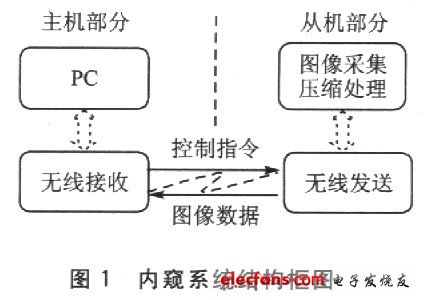
As shown in Figure 1, the wireless endoscope system is mainly composed of a host and a slave (wireless endoscope). The slave machine collects the original image from the camera, and after compression processing, the compressed image data is transmitted to the host computer wirelessly; the host computer connects to the Bluetooth adapter to receive the compressed image and forwards it to the management software on the PC. The management software decompresses the image And show it.
1.2 Composition structure of wireless endoscope
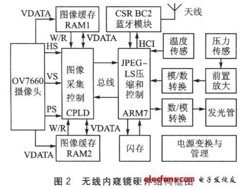
As shown in Figure 2, the wireless endoscope uses the CPLD chip EPM7256-144 to realize the image acquisition control of the 300,000-pixel CMOS camera OV7660 and the switching of data and address buses. Atmel's ARM7 chip AT91R40008 is used to realize JPEG-LS lossless image compression and Bluetooth wireless data transmission, to achieve temperature and pressure acquisition, and controllable light source and system control. The image data exchange between CPLD and ARM7 is realized through an 8-bit data bus, and the handshake control between ARM7 and CPLD is realized through an I / O line. Due to the large amount of image data, hundreds of thousands of bytes are calculated according to the format of 640 & TImes; 480 resolution and 8-bit images. Therefore, the system externally expands 2 pieces of 512KB SRAM used in ping pong mode as data cache.
1.3 The working principle of the system
The endoscopic system can achieve continuous image acquisition and control of temperature, humidity, lighting brightness, etc. Image acquisition is the core of the system, and its workflow is as follows:
â‘ By default, the system works in sleep state.
â‘¡The staff sends commands through the PC management software to start collecting images, and the software sends the commands to the Bluetooth adapter through the USB interface and then to the wireless endoscope.
â‘¢After the endoscope receives the image acquisition command, the ARM controls the CPLD to start acquiring image data.
â‘£ CPLD writes the collected image data into a SRAM, switches the ARM bus to the SRAM, and informs ARM to compress it; at the same time, CPLD continues to collect the next frame image into another SRAM, which is convenient for improving the throughput of the system rate.
⑤ The ARM returns a response command through the Bluetooth module and returns the header information of the JPEG-LS image.
â‘¥ The PC management software sends a command to receive the compressed image of the next line, ARM compresses the original image of the line, and sends the compressed data; if an error occurs, it can be sent again. Repeat this step to obtain a full frame compressed image.
⑦ The PC software decodes and displays the compressed image, and provides other additional functions, such as image processing and saving.
⑧ Repeat steps ② ~ ⑦ to obtain the next frame of compressed image.
It can be seen from the above process that JPEG-LS compression and wireless channel transmission determine the image transmission rate of the entire system. The wireless transmission adopts Bluetooth technology, and its nominal air rate is 1 Mbps, which is not easy to improve; therefore, the core of the system design is the coding efficiency of JPEG-LS.
SHENGYA LIGHTING TECHNOLOGY CO., LTD. , https://www.syalighting.com