Abstract: Click sound refers to the noise generated by the audio transient signal in headphones or speakers during the opening or closing of the amplifier driving the converter. Until now, the industry has still subjectively evaluated this click. Descriptions such as "lower clicks" and "working without clicks" represent subjective judgments about the quantitative analysis of clicks. In order to eliminate the subjective judgment factors that measure the performance of audio amplifiers, Maxim has determined objective indicators that describe clicks. This article describes the test process of this indicator KCP and this parameter.
Introduction The special requirements of portable audio equipment are the key to product design. Product A is better than its competitor B, and what is the reason for its more ideal use? From a performance point of view, the frequency response flatness and THD + N between competitors The indicators are not much different, and it is difficult to distinguish which product has better performance. The main differences in products can be judged from the user interface, but this depends largely on subjective evaluation. We can use objective audio performance indicators to compare products and explain why one product is clearly superior to other products.
An important indicator for evaluating audio performance is the "click" or other strange transient noise that occurs when the device is turned on or off. With the improvement of people's expectations for product performance, no transient noise has become an important indicator for people to choose products, and it is also a key selling point for portable audio equipment. Until now, the industry has still subjectively evaluated this click sound, and descriptions such as "lower click sound" and "working without click sound" represent subjective judgments on quantitative analysis of click sound. However, the user's expectations are changing, and designers need to get objective indicators for judging clicks.
This article describes a method for quantitatively representing click parameters, which can be used to compare products repeatedly in different products. The characteristics of click sound Click sound refers to the audio transient signal that appears in headphones or speakers when the amplifier drives the converter on or off. In portable applications, reducing power consumption is the key to extending battery life. When certain functional modules are not required to work, these modules are generally disabled. This function may further highlight the adverse factor of clicks. When the device is turned on or off, the ideal component should not have audio output, and in practical applications, all audio amplifiers will produce a clicking sound. Depending on the sensitivity of the converter (speaker or headphones) used, the distance between the converter and the human ear, the ability of the amplifier to handle transient signals, and the sensitivity of hearing, no clicks can be heard. Although many factors are involved in determining the audio threshold, the output performance of the amplifier (which has nothing to do with the audio transfer function) can be used to quantitatively compare the performance of the product.
Table 1 lists the factors that may cause amplifier signal transients.
Table 1. Factors causing amplifier transient noise
Maxim divides audio testing into two categories to measure KCP measurements reasonably. Referring to Table 1 above, items 1 (power on) and 2 (power off) belong to category A. It is generally assumed that under normal operating conditions, Maxim products with SHDN function have a transient mode controlled by the shutdown pin (or register bit) at power-up. Class A does not represent normal use, it is only relevant when measuring those software controls that cannot turn off the device. Items 3 and 4 (Type B measurement) are closer to normal usage.
Figures 1 and 2 (in the time domain) show the transient process of two different headphone amplifiers exiting the off state. The first AC-coupled headphone amplifier and the second DC-coupled headphone amplifier are compared. When the amplifier is turned off, it generates a large transient (Figure 1). This transient produces a significant low-frequency sound because of its slow turn-on process. (Note that the time scale is 100ms / div.)
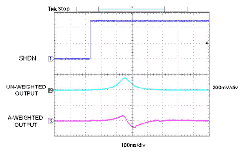
Figure 1. The data shows the transient process when a good-performance AC-coupled headphone amplifier exits the off state. The amplitude is large, and although this transient process will produce a pronounced bass signal, the human ear is not sensitive to this sound.
The second transient process, the DC-coupled headphone amplifier (Figure 2), appears to be submerged in the oscilloscope's noise floor before A-weighted filtering. For this type of amplifier, most of the audio comes from the DC offset voltage that is generated from shutdown to full operation. Since the offset is only a few millivolts, the unfiltered signal cannot accurately determine the size of the click. After adopting A-weighted filtering, the click noise generated by the offset of the DC-coupled headphone amplifier is extracted from the noise floor to obtain a more objective measurement result. (Note that the filtered signal scale V / div is not displayed.)
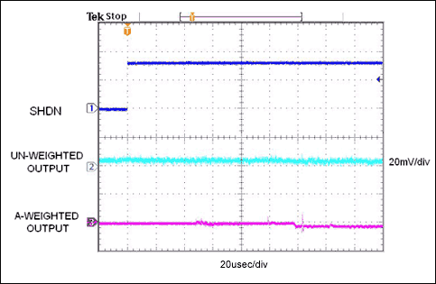
Figure 2. The data shows the transient process of the low-offset, DC-coupled headphone amplifier exiting the off state. Compared to Figure 1A, the amplitude is much lower (thus, subjectively feels much lower noise), and the amplifier is fully turned on after 150µs.
When analyzing this issue, two aspects need to be considered. First, how to measure transients objectively? Secondly, if necessary, what standards are used to measure the test results? Click Test Method Maxim uses Audio Precision's System 1 and System 2 (recommended) audio analyzers to measure click (Figure 3) Similar test equipment from other manufacturers can also be used. The recommended index KCP can objectively measure the click of the audio amplifier.
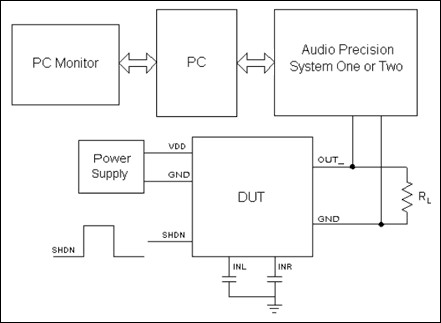
Figure 3. Test device for the click sound of the headphone amplifier. Note that the left and right channel input pins are AC-coupled to ground. The output load is the typical headphone impedance. A square wave generator is used to trigger the shutdown pin.
When starting the measurement, connect the output of the device under test (DUT) to the load or the simulated load (dummy load). Load the required SHDN and power supply on the DUT and AC-couple all DUT inputs to ground. No input signal is required; input excitation includes control signals for the DUT to switch between various working or stop working modes. Connect the DUT output to the analog analysis section of the audio analyzer.
Next, select the analyzer's A-weighted filter (recommended) or unweighted 22Hz to 22kHz filter to limit the measurement bandwidth to the audio range. Note that the fast high-level transients of the oscilloscope do not indicate how much energy appears in the audio frequency band. The human ear's frequency response to speakers or headphones transient signals is very limited. Therefore, adding A-weighted filtering (Figure 4) is more conducive to analysis because it enhances the sensitive frequency components of the human ear. Some audio analyzers cannot use A weighting. In this case, the bandwidth of the frequency response of the human ear should be limited. The bandwidth limit commonly used in audio test equipment is 22Hz to 22kHz, and the bandwidth limit filter can achieve a flat response of 20kHz (usually the upper limit of the human ear).
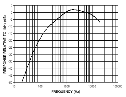
Figure 4. Frequency response of an A-weighted filter. Frequency equalization is close to the sensitive range of the ear, so this parameter is usually used for noise measurement. Note that the filter transfer function is unity gain (0dB) @ 1kHz, and the frequency signals at both ends are attenuated.
Set the detector to the peak reading (not the RMS value), and set the detector to sample 32 times per second. For the transient and other signals we want to collect, RMS detection has no effect. The System 2 analyzer supports a higher sampling rate, while the 32 sampling rate per second can get the same measurement options from the System 1 audio analyzer. (The 32 sampling rate per second is the fastest acquisition setting in the System 1 model.) Disable the automatic range adjustment circuit of the audio analyzer, and manually select to accurately track the expected peak signal amplitude. The range of System 1 and System 2 analyzers is 1 to 1024 times (0 to 60.21dB), and the step size is 4 times (12.04dB). In order to achieve accurate measurement, it is recommended to use the 1X / Y range as the starting point of the click measurement of the audio amplifier.
Drive the SHDN pin with a low-frequency square wave for repeated measurements. The SHDN cycle frequency is lower than the audio frequency band, and the period should be long enough to ensure that all turn-on and turn-off events can be collected (some models have a long turn-on delay). Maxim usually chooses a 0.5 Hz period.
When transients occur between operation and shutdown, the analyzer's histogram option makes it easy to monitor DUT transients. The peak voltage can be easily determined and the histogram can be quickly reset during the measurement. The peak voltage is recorded in dBV (dB value relative to 1V). This indicator is KCP. Importance of test equipment The above test methods can support the comparison of similar devices and produce reproducible objective results. The test equipment is best able to maintain a linear response to any size input. For example, the peak reading when testing a 1mV shock response should be 40dB lower than a 100mV shock with the same pulse width. (See Appendix Test Transient Calibration).
An oscilloscope with external filtering can be used in this click measurement scheme. However, experience shows that the typical value of high-quality headphone amplifiers is in the millivolt range, which makes it difficult for most oscilloscopes to make accurate measurements. You can use an oscilloscope to test higher voltage equipment such as high-power amplifiers. The average value repeated testing of different devices of the same model may produce different test results. Therefore, multiple devices should be tested to balance this difference before determining the performance of a certain model. For a well-designed DC-coupled headphone amplifier, most clicks are proportional to the input offset voltage, and unless equalized (or otherwise eliminated), the input offset voltage varies from device to device. When fully testing a model, to ensure the consistency of the results, the transients of each operating mode should be measured multiple times. Then, calculate the average. If the device is about to be put into use, it is recommended to make multiple measurements. Test all channels of stereo or multi-channel products. Establishing the absolute voltage level should specify the absolute voltage level of the click sound according to the actual application of the amplifier. For example, suppose a device produces a transient of -50dBV when it is turned off. If the DUT is a 50W / 8Ω power amplifier, the full scale is + 29dBV. In this way, the ratio of the click sound that the amplifier can detect to the maximum peak voltage is:
-(+ 29-(-50)) = -79dB
However, if the DUT is a 20mW / 16Ω headphone amplifier, the full-scale range is about -1.9dBV, which will be smaller than the peak voltage ratio: -48.1dB. Setting the indicator level Although we have explained how to obtain an objective measurement method for the click indicator, there is still a question: how accurate is it?
Consider the following issues. After measuring the two headphone amplifiers using the above method, you get repeatable Class B click suppression results. The first amplifier has a KCP of -59dBV and the second is -61dBV. Is the noise of the second amplifier much smaller than the first one? Or, are both results acceptable? The measurement results are objective, but the understanding of "acceptable" is still subjective.
An acceptable and detectable level of click suppression depends on a number of factors: the efficiency of the headphones / speaker under test, the typical distance from the ear to the converter, the SHDN cycle frequency, and the background noise level when listening, etc. .
In many applications, although many factors affect the establishment of acceptable click levels, we can still specify a credible benchmark. Note that the test results of the Class B click sound of the Maxim headphone amplifier (Table 2), all tests use a 32Ω load resistor, and each KCP value represents the average of four samples per port.
Table 2. KCP value of headphone amplifier (A-weighted, 32 times / sec, peak voltage, 32Ω load)
The above data is Maxim's test result of KCP performance. To eventually eliminate subjective factors in amplifier performance testing, Maxim recommends that other semiconductor suppliers use this method and defined KCP parameters. For more information about this test, please visit the following link Maxim Audio Product Information Maxim Audio Discussion Group For audio test and measurement standards, please visit: Audio Precision World Network. A similar article was published in the March 2005 issue of EDN.
1 Other manufacturers of similar equipment include Rhode & Schwartz (audio analyzer) and Prism Sound (dScope). appendix. Calibrating Equivalent Equipment The objective test solution to obtain click performance indicators in this application note uses Audio Precision's System 1 and System 2 audio analyzers. If there is no system 1 or system 2 analyzer, you can use the following methods.
KCP performance measurement can be achieved using equivalent test equipment provided by other manufacturers. Figure A shows the general test setup of the audio analyzer and DUT.
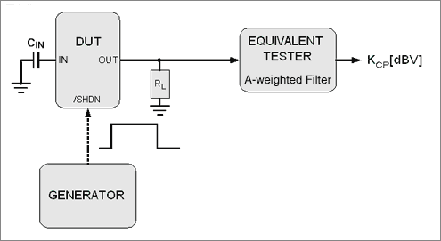
Figure A. Click test device for equivalent test equipment from other manufacturers
Before recording the test results and directly comparing the results, the test device should be calibrated. In addition, it is necessary to verify the total energy recorded by the equivalent analyzer. In fact, this record has a linear relationship with the input amplitude. Only in this way can the energy of the click sound be accurately recorded, especially when there is a rapid rise transient in the audio frequency band. Simple calibration requires a function generator and an equivalent analyzer. (Refer to the example in Figure B.) Perform the following steps to calibrate: Load a 0.5Hz square wave with a known amplitude at the input of the equivalent audio analyzer. Set an equivalent analyzer to detect the A-weighted peak voltage. Record the peak voltage readings of various input signal amplitudes.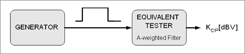
Figure B. Equivalent audio analyzer calibration test device. Calibration must be performed to ensure that the total energy recorded by the same analyzer is linear with various input amplitudes.
Table A below shows the calibration results of System 2 Audio Precision audio analyzer set to A-weighted, 32 samples per second. 1X / Y automatic range is set to 1mVP-P to 40mVP-P input signal produces a 6dB weighting factor. The 6dB weighting factor is related to the A-weighted restricted transfer function of the Audio Precision analyzer. When the input signal is greater than 40mVP-P, the calibration result becomes non-linear for this particular setting. This range is suitable for most amplifiers.
Table A. Audio Precision System 2 calibration results
This calibration measure can be applied to equivalent analyzers to ensure accurate click performance measurement. In addition, after determining the same calibration value and the appropriate input signal range, the same audio analyzer can be used to accurately compare the click performance indicators of the two amplifiers.
An important indicator for evaluating audio performance is the "click" or other strange transient noise that occurs when the device is turned on or off. With the improvement of people's expectations for product performance, no transient noise has become an important indicator for people to choose products, and it is also a key selling point for portable audio equipment. Until now, the industry has still subjectively evaluated this click sound, and descriptions such as "lower click sound" and "working without click sound" represent subjective judgments on quantitative analysis of click sound. However, the user's expectations are changing, and designers need to get objective indicators for judging clicks.
This article describes a method for quantitatively representing click parameters, which can be used to compare products repeatedly in different products. The characteristics of click sound Click sound refers to the audio transient signal that appears in headphones or speakers when the amplifier drives the converter on or off. In portable applications, reducing power consumption is the key to extending battery life. When certain functional modules are not required to work, these modules are generally disabled. This function may further highlight the adverse factor of clicks. When the device is turned on or off, the ideal component should not have audio output, and in practical applications, all audio amplifiers will produce a clicking sound. Depending on the sensitivity of the converter (speaker or headphones) used, the distance between the converter and the human ear, the ability of the amplifier to handle transient signals, and the sensitivity of hearing, no clicks can be heard. Although many factors are involved in determining the audio threshold, the output performance of the amplifier (which has nothing to do with the audio transfer function) can be used to quantitatively compare the performance of the product.
Table 1 lists the factors that may cause amplifier signal transients.
Table 1. Factors causing amplifier transient noise
| 1. | Powered up (power applied) | Category A |
| 2. | Powered down (power removed) | |
| 3. | Brought out of shutdown (power applied previously) | Category B |
| 4. | Forced into shutdown (power sTIll applied) |
Maxim divides audio testing into two categories to measure KCP measurements reasonably. Referring to Table 1 above, items 1 (power on) and 2 (power off) belong to category A. It is generally assumed that under normal operating conditions, Maxim products with SHDN function have a transient mode controlled by the shutdown pin (or register bit) at power-up. Class A does not represent normal use, it is only relevant when measuring those software controls that cannot turn off the device. Items 3 and 4 (Type B measurement) are closer to normal usage.
Figures 1 and 2 (in the time domain) show the transient process of two different headphone amplifiers exiting the off state. The first AC-coupled headphone amplifier and the second DC-coupled headphone amplifier are compared. When the amplifier is turned off, it generates a large transient (Figure 1). This transient produces a significant low-frequency sound because of its slow turn-on process. (Note that the time scale is 100ms / div.)
Figure 1. The data shows the transient process when a good-performance AC-coupled headphone amplifier exits the off state. The amplitude is large, and although this transient process will produce a pronounced bass signal, the human ear is not sensitive to this sound.
The second transient process, the DC-coupled headphone amplifier (Figure 2), appears to be submerged in the oscilloscope's noise floor before A-weighted filtering. For this type of amplifier, most of the audio comes from the DC offset voltage that is generated from shutdown to full operation. Since the offset is only a few millivolts, the unfiltered signal cannot accurately determine the size of the click. After adopting A-weighted filtering, the click noise generated by the offset of the DC-coupled headphone amplifier is extracted from the noise floor to obtain a more objective measurement result. (Note that the filtered signal scale V / div is not displayed.)
Figure 2. The data shows the transient process of the low-offset, DC-coupled headphone amplifier exiting the off state. Compared to Figure 1A, the amplitude is much lower (thus, subjectively feels much lower noise), and the amplifier is fully turned on after 150µs.
When analyzing this issue, two aspects need to be considered. First, how to measure transients objectively? Secondly, if necessary, what standards are used to measure the test results? Click Test Method Maxim uses Audio Precision's System 1 and System 2 (recommended) audio analyzers to measure click (Figure 3) Similar test equipment from other manufacturers can also be used. The recommended index KCP can objectively measure the click of the audio amplifier.
Figure 3. Test device for the click sound of the headphone amplifier. Note that the left and right channel input pins are AC-coupled to ground. The output load is the typical headphone impedance. A square wave generator is used to trigger the shutdown pin.
When starting the measurement, connect the output of the device under test (DUT) to the load or the simulated load (dummy load). Load the required SHDN and power supply on the DUT and AC-couple all DUT inputs to ground. No input signal is required; input excitation includes control signals for the DUT to switch between various working or stop working modes. Connect the DUT output to the analog analysis section of the audio analyzer.
Next, select the analyzer's A-weighted filter (recommended) or unweighted 22Hz to 22kHz filter to limit the measurement bandwidth to the audio range. Note that the fast high-level transients of the oscilloscope do not indicate how much energy appears in the audio frequency band. The human ear's frequency response to speakers or headphones transient signals is very limited. Therefore, adding A-weighted filtering (Figure 4) is more conducive to analysis because it enhances the sensitive frequency components of the human ear. Some audio analyzers cannot use A weighting. In this case, the bandwidth of the frequency response of the human ear should be limited. The bandwidth limit commonly used in audio test equipment is 22Hz to 22kHz, and the bandwidth limit filter can achieve a flat response of 20kHz (usually the upper limit of the human ear).
Figure 4. Frequency response of an A-weighted filter. Frequency equalization is close to the sensitive range of the ear, so this parameter is usually used for noise measurement. Note that the filter transfer function is unity gain (0dB) @ 1kHz, and the frequency signals at both ends are attenuated.
Set the detector to the peak reading (not the RMS value), and set the detector to sample 32 times per second. For the transient and other signals we want to collect, RMS detection has no effect. The System 2 analyzer supports a higher sampling rate, while the 32 sampling rate per second can get the same measurement options from the System 1 audio analyzer. (The 32 sampling rate per second is the fastest acquisition setting in the System 1 model.) Disable the automatic range adjustment circuit of the audio analyzer, and manually select to accurately track the expected peak signal amplitude. The range of System 1 and System 2 analyzers is 1 to 1024 times (0 to 60.21dB), and the step size is 4 times (12.04dB). In order to achieve accurate measurement, it is recommended to use the 1X / Y range as the starting point of the click measurement of the audio amplifier.
Drive the SHDN pin with a low-frequency square wave for repeated measurements. The SHDN cycle frequency is lower than the audio frequency band, and the period should be long enough to ensure that all turn-on and turn-off events can be collected (some models have a long turn-on delay). Maxim usually chooses a 0.5 Hz period.
When transients occur between operation and shutdown, the analyzer's histogram option makes it easy to monitor DUT transients. The peak voltage can be easily determined and the histogram can be quickly reset during the measurement. The peak voltage is recorded in dBV (dB value relative to 1V). This indicator is KCP. Importance of test equipment The above test methods can support the comparison of similar devices and produce reproducible objective results. The test equipment is best able to maintain a linear response to any size input. For example, the peak reading when testing a 1mV shock response should be 40dB lower than a 100mV shock with the same pulse width. (See Appendix Test Transient Calibration).
An oscilloscope with external filtering can be used in this click measurement scheme. However, experience shows that the typical value of high-quality headphone amplifiers is in the millivolt range, which makes it difficult for most oscilloscopes to make accurate measurements. You can use an oscilloscope to test higher voltage equipment such as high-power amplifiers. The average value repeated testing of different devices of the same model may produce different test results. Therefore, multiple devices should be tested to balance this difference before determining the performance of a certain model. For a well-designed DC-coupled headphone amplifier, most clicks are proportional to the input offset voltage, and unless equalized (or otherwise eliminated), the input offset voltage varies from device to device. When fully testing a model, to ensure the consistency of the results, the transients of each operating mode should be measured multiple times. Then, calculate the average. If the device is about to be put into use, it is recommended to make multiple measurements. Test all channels of stereo or multi-channel products. Establishing the absolute voltage level should specify the absolute voltage level of the click sound according to the actual application of the amplifier. For example, suppose a device produces a transient of -50dBV when it is turned off. If the DUT is a 50W / 8Ω power amplifier, the full scale is + 29dBV. In this way, the ratio of the click sound that the amplifier can detect to the maximum peak voltage is:
-(+ 29-(-50)) = -79dB
However, if the DUT is a 20mW / 16Ω headphone amplifier, the full-scale range is about -1.9dBV, which will be smaller than the peak voltage ratio: -48.1dB. Setting the indicator level Although we have explained how to obtain an objective measurement method for the click indicator, there is still a question: how accurate is it?
Consider the following issues. After measuring the two headphone amplifiers using the above method, you get repeatable Class B click suppression results. The first amplifier has a KCP of -59dBV and the second is -61dBV. Is the noise of the second amplifier much smaller than the first one? Or, are both results acceptable? The measurement results are objective, but the understanding of "acceptable" is still subjective.
An acceptable and detectable level of click suppression depends on a number of factors: the efficiency of the headphones / speaker under test, the typical distance from the ear to the converter, the SHDN cycle frequency, and the background noise level when listening, etc. .
In many applications, although many factors affect the establishment of acceptable click levels, we can still specify a credible benchmark. Note that the test results of the Class B click sound of the Maxim headphone amplifier (Table 2), all tests use a 32Ω load resistor, and each KCP value represents the average of four samples per port.
Table 2. KCP value of headphone amplifier (A-weighted, 32 times / sec, peak voltage, 32Ω load)
| Part Number | KCP | Comments | |
| Into SHDN (dBV) | Out of SHDN (dBV) | ||
| MAX9750C Headphone Amp | -55.8 | -47.9 | + 3dB gain setTIng |
| MAX9760 Headphone Amp | -57.4 | -56.2 | Unity gain, 15k |
| MAX4410 | -69.9 | -77.8 | Unity gain, 10k |
| MAX4299 | -59.1 | -49.4 | Category A (no SHDN) |
The above data is Maxim's test result of KCP performance. To eventually eliminate subjective factors in amplifier performance testing, Maxim recommends that other semiconductor suppliers use this method and defined KCP parameters. For more information about this test, please visit the following link Maxim Audio Product Information Maxim Audio Discussion Group For audio test and measurement standards, please visit: Audio Precision World Network. A similar article was published in the March 2005 issue of EDN.
1 Other manufacturers of similar equipment include Rhode & Schwartz (audio analyzer) and Prism Sound (dScope). appendix. Calibrating Equivalent Equipment The objective test solution to obtain click performance indicators in this application note uses Audio Precision's System 1 and System 2 audio analyzers. If there is no system 1 or system 2 analyzer, you can use the following methods.
KCP performance measurement can be achieved using equivalent test equipment provided by other manufacturers. Figure A shows the general test setup of the audio analyzer and DUT.
Figure A. Click test device for equivalent test equipment from other manufacturers
Before recording the test results and directly comparing the results, the test device should be calibrated. In addition, it is necessary to verify the total energy recorded by the equivalent analyzer. In fact, this record has a linear relationship with the input amplitude. Only in this way can the energy of the click sound be accurately recorded, especially when there is a rapid rise transient in the audio frequency band. Simple calibration requires a function generator and an equivalent analyzer. (Refer to the example in Figure B.) Perform the following steps to calibrate: Load a 0.5Hz square wave with a known amplitude at the input of the equivalent audio analyzer. Set an equivalent analyzer to detect the A-weighted peak voltage. Record the peak voltage readings of various input signal amplitudes.
Figure B. Equivalent audio analyzer calibration test device. Calibration must be performed to ensure that the total energy recorded by the same analyzer is linear with various input amplitudes.
Table A below shows the calibration results of System 2 Audio Precision audio analyzer set to A-weighted, 32 samples per second. 1X / Y automatic range is set to 1mVP-P to 40mVP-P input signal produces a 6dB weighting factor. The 6dB weighting factor is related to the A-weighted restricted transfer function of the Audio Precision analyzer. When the input signal is greater than 40mVP-P, the calibration result becomes non-linear for this particular setting. This range is suitable for most amplifiers.
Table A. Audio Precision System 2 calibration results
| VIN (mVP-P) | VTHEORETICAL (dBV) | VREADING (dBV) | A-Weighted CalibraTIon |
| 1 | -60.000 | -66.295 | 6.295 |
| 5 | -46.021 | -52.391 | 6.370 |
| 10 | -40.000 | -46.186 | 6.186 |
| 20 | -33.979 | -39.883 | 5.904 |
| 40 | -27.958 | -34.120 | 6.162 |
| 60 | -24.437 | -32.140 | 7.703 |
| 80 | -21.938 | -30.791 | 8.853 |
| 100 | -20.000 | -28.747 | 8.747 |
This calibration measure can be applied to equivalent analyzers to ensure accurate click performance measurement. In addition, after determining the same calibration value and the appropriate input signal range, the same audio analyzer can be used to accurately compare the click performance indicators of the two amplifiers.
Grille Led Panel Light is the new style among the panel lights. We are the manufacturer of producing energy saving interior lighting. This type of led grille light is in high quality and easy to install. There are three color temperatures with cool white, warm white and natural white of panel lights. It is used by non-isolated driver and built-in driver. The unique feature of the grille panel light is divided in double head and four head. These grille panels are mainly apply to home, office and school, etc.
Grille LED Panel Light
Four Headed Grille Light,Led Embedded Grille Panel Light,Square Grille Panel Light,Ceiling Grille Led Panel Light
Jiangmen Lika Lighting Electrical Appliances Co., Ltd , https://www.lika-led.com