Abstract: Introduce a low-noise amplifier design for passive micro-antenna for aerospace GPS receivers. The content involves selecting the input matching network of the low-noise amplifier and optimizing the matching parameters; and verifying the effectiveness of its application in the antenna through actual tests. The experimental results show that the performance is better than the existing spaceborne GPS receiver antennas.
Global Positioning System GPS (Global PosTITIoning System) is a passive positioning system that can be applied to both sea, land, air, and sky motion and stationary carriers. Research data shows that the GPS receiver's single-point real-time positioning accuracy is not lower than the ground application level in low-Earth orbit below 900km. The aerospace applications of GPS are affecting the structure of future spacecraft systems. The application of GPS technology to spacecraft has a significant effect on the reduction of spacecraft cost, power consumption, and weight. GPS can complete the functions of various sensors, determine the spacecraft's track, attitude, time parameters and the relative distance between the spacecraft. The final result can reduce the number of sensor accessories on the spacecraft and enhance the spacecraft's autonomous operation Ability [1]. 
The aerospace GPS receiver is an L1 C / A code navigation type receiver, and only receives L1 C / A signals. For receivers on the ground, the minimum received power of the L1 C / A signal is -160.0 dBw [2], and the useful signal is submerged in the thermal noise signal. In LEO orbit, the free space propagation loss and atmospheric loss are considered to be smaller than those on the ground, so the GPS signal power is 1-7dBw greater than the ground. After the signal received by the receiver is down-converted, baseband processing is performed at a lower intermediate frequency. Usually the signal strength received by the passive antenna does not meet the input requirements of the inverter chip, so a low noise amplifier should be used to amplify the signal received by the antenna. The low-noise amplifier must meet the gain requirements and the noise figure should be as small as possible.
1 LAN design
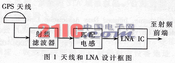
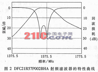
The block diagram of the antenna and LAN design is shown in Figure 1. All departments are integrated together to reduce feeder losses and reduce noise figure. According to the aerospace application characteristics of the designed aerospace GPS receiver, the Micropulse1621LW passive antenna is selected. It is simple, rugged, and small in size, and is suitable for installation on micro satellites. At the receiver antenna, the GPS signal is very weak, and the out-of-band RF signal affects the LAN and RF front-end operation, causing signal distortion. Especially when the distance between the GPS antenna and the radio frequency antenna is relatively short, the radiation of the radio frequency antenna may cause the device to saturate and the GPS receiver may not work properly. Therefore, a radio frequency filter is needed to suppress the out-of-band signal. This design selects MuRata's filter DFC21R57P002HA, whose characteristics are shown in Figure 2. 
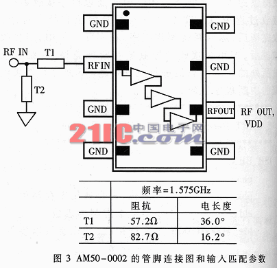
The low-noise preamplifier of the aerospace GPS receiver is designed with the AM50-0002 low-noise amplifier. The noise figure of AM50-0002 is 1.15B, the nominal gain is 27dB, and a chip can meet the requirements [3]. The pin connection diagram of AM50-0002 and the input matching parameters are shown in Figure 3. Considering the complexity of using microstrip to achieve input matching and the applicability of microwave inductance at 1.575 GHz frequency, microwave inductance is used to achieve input matching in the design. The input matching inductance network and inductance parameters are optimized by ADS.
2 Matching network and parameter optimization
(1) Calculate the parameters of microstrips T1 and T2
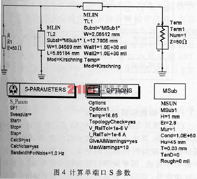
Microwave EDA tool software ADS2002 was used to calculate the parameters of microstrips T1 and T2. Execute the command ADS2002 → Tools → LineCalc, select the micro-determination type, substrate parameters (substrate parameters) and working frequency, fill in the impedance and electrical length in Figure 3 under the electrical parameters (Elactrical), perform synthesis (Synthesize), from the physical Under the parameter (Physical), the width W and length L of the microstrip are obtained. The calculation results of T1 and T2 in Figure 3 are as follows:
T1 W = 2.08512mm, L = 12.7706mm;
T2 W = 1.04589mm, L = 5.85184mm. 
(2) Calculate single-port S parameters
According to the schematic diagram shown in Figure 4, the microstrip is set to the parameters obtained in (1), the microstrip type, substrate parameters and operating frequency are consistent with (1), and the single-port S parameter is calculated as S (1, 1 ) = 0.756 / 62.140.
(3) Determine the inductance matching network
Try different inductance matching networks, and determine the matching network according to the matching results as shown in Figure 5. 
(4) Optimize matching parameters
The principle circuit is shown in Figure 5, and S (1,1) = 0.756 / 62.140 is taken as the optimization goal to optimize the parameters of ideal inductance L1, L2. The result is obtained after 36 steps of optimization calculation. At this time, the S parameter is S (1,1) = 0.758 / 62.042, and the ideal inductance parameters obtained are: L1 = 4.986nH, L2 = 5.302nH.
Figure 5
3 Measured results
The antenna obtained in this design and the other two antennas are connected to work with the Super Star OEM receiver respectively. The antenna obtained in this design has similar performance to the SM25 antenna commonly used in ground applications, which is better than the existing engineering satellite GPS receiver antenna.
Custom Medical Cable Assemblies,Custom Medical Wire,Custom ECG Cable,Custom Sensor Cable
Dong guan Sum Wai Electronic Co,. Ltd. , http://www.sw-cables.com