With the continuous improvement of living standards and the increasing proportion of urban aging, the familyization of medical electronic devices has gradually become a trend. Among them, home electronic blood pressure monitor is one of the typical home medical testing equipment. Electronic sphygmomanometers have many advantages and are increasingly popular with ordinary families. This paper introduces the design of the home electronic sphygmomanometer with MSP430F449 as the control core, supplemented by analog signal processing circuit between BP01 pressure sensor and MCU, LCD display and voice prompt.
The main principle of the single-chip microcomputer is: PWM output control air pump air leakage to adjust the air pressure in the cuff; one ADC samples the air pressure DC component in the cuff to obtain systolic pressure and diastolic pressure; one-way ADC sampling cuff air pressure AC component is analyzed and calculated to determine the contraction The transient time position of the pressure and diastolic pressure; receiving the blood pressure pulse signal triggers the ADC operation; outputs the calculated systolic pressure and diastolic blood pressure results to the LCD display and performs a numerical voice prompt.
MSP430FF449D microcontroller main control circuit
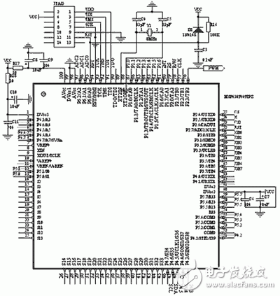
The main control circuit of this system is shown in Figure 1. It is mainly composed of MSP430F449 chip, JTAG interface circuit, clock generation circuit, clock output circuit, reset circuit, PWM wave output circuit and power supply circuit. The JTAG is used to download and debug the program, and the PWM wave output circuit is used to control the air pump. When measuring blood pressure, first inflate to a height of 200 mmHg, and then slowly deflate at a rate of about 5 mmHg per second. Achieve automatic measurement of blood pressure.

Figure 1 electronic sphygmomanometer main control circuit
Blood pressure sensing circuit
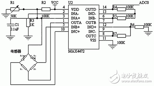
As shown in Figure 2, this circuit uses the BP01 pressure sensor and the op amp MAX4472.

Figure 2 blood pressure sensing circuit
The BP01 pressure sensor is specifically designed to detect blood pressure and is mainly used in portable electronic blood pressure monitors. It is made of precision thick film ceramic chip and nylon plastic package. It features high linearity, low noise and low external stress. It adopts internal calibration and temperature compensation to improve measurement accuracy, stability and repeatability. The accuracy is ±1% and the zero offset is no more than ±300μV. The MAX4472 is a low-power amplifier chip from MAXIM that integrates four operational amplifiers. In this system, the internal integrated operational amplifier A is connected to a constant current source to provide a constant current for the pressure sensor. The operational amplifier B and the operational amplifier C form an differential input, single-ended output amplification circuit, and directly input ADC0 to monitor the blood pressure DC component.
Filtering and amplifying circuit
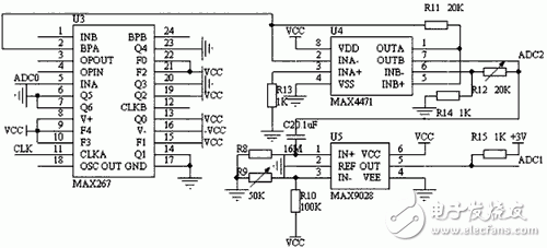
As shown in Figure 3, the circuit consists of two parts: filtering and amplification. The MAX267 is an integrated filter produced by MAXIM. It can be used in low-pass, band-pass, high-pass, and other modes. It is flexible and performs much better than the filter circuit composed of integrated op amps.

Figure 3 Filter and Amplifier Circuit
The MAX4471 is a low-power amplifier from MAXIM. The MAX9028 is a low-power comparator from MAXIM. The filter circuit uses MAX267 to form a bandpass filter (allowing the signal of 0.8~38Hz to pass), filtering out the DC component and power supply in the signal, and the high frequency noise and power frequency interference of the skin and cuff friction, and then further amplified by the MAX4471. Get the voltage signal matched by the microcontroller, enter ADC2, monitor the AC component of blood pressure. At the same time, the signal is converted into a pulse signal by the low-power comparator MAX9028, which triggers the operation of ADC1.
Edit Comment: This paper gives the design of portable electronic sphygmomanometer circuit design, and based on MSP430F449 for the control core with pressure sensor and peripheral analog circuit and LCD driver chip to achieve the design of electronic sphygmomanometer. The electronic sphygmomanometer has the advantages of miniaturization, low power consumption, and high degree of intelligence, and is portable and easy to operate in use, thereby showing a trend of householdization.
Electronic enthusiast "Smart Medical Special", more quality content, download now

Take home GLAREME Advanced Multifunctional blender that expands your culinary horizons and kitchen functions.Our versatile mixer can grind, stir, mash, mince and control the process perfectly.Multifunctional high-speed smoothie mixer for large groups and families making smoothies, juices, frozen beverages, milkshakes, sauces and soups is an ideal gift for choosing kitchen utensils.With a small grinding cup, you can also grind whole grains.GLAREME mixer is your best choice.
Multifunction Blender,Electric Juice Blender,Small Electric Blender,Best Multi Function Blender
Jiangmen Taifai Technology Co.,Ltd , https://www.glaremecn.com