Design of temperature acquisition system based on zigBee wireless network
Abstract: Aiming at the wiring problem of the traditional distributed temperature monitoring system, the realization scheme of using ZigBee wireless network technology to realize the distributed temperature detection system is proposed. This solution successfully established a large-scale three-dimensional zigBee wireless network through the wireless design of ZigBee technology-based wireless transceiver microprocessor CC2430 and the hardware design and software design process of the coordinator node and sensor node. Temperature monitoring makes the detection process very simple and effective.
0 Introduction In many application systems such as grain depot temperature control system, cold store temperature control system, intelligent building control system, central air conditioning system, etc., a multi-point distributed temperature measurement system is needed. The traditional multi-point distributed temperature measurement system mostly uses the wired transmission method, which requires a lot of wiring in the field, which brings a lot of inconvenience to the deployment, maintenance, update and upgrade of the system. The warehouse temperature monitoring system designed in this paper uses the wireless communication network of ZigBee technology to continuously monitor the temperature of each point of the warehouse for 24 hours, so that the manager can always know the temperature information of the warehouse site in the control room.
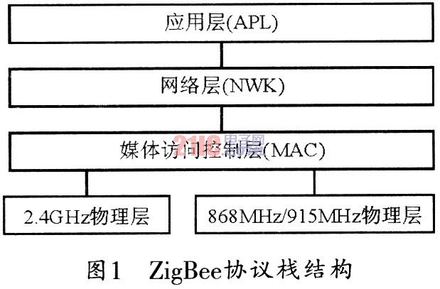
1 ZigBee wireless network ZigBee is an emerging short-range, low-rate wireless network technology. It is a wireless technology solution between wireless tags and Bluetooth. The basis of ZigBee is IEEE 802. 15.4, which specifies the physical layer and media access control layer of ZigBee. ZigBee's working frequency bands are 868 MHz, 915 MHz, and 2.4 GHz, respectively. The frequency band 868 MHz defines 1 channel: the frequency band 915 MHz defines 10 channels; the frequency band 2.4 GHz defines 16 channels. ZigBee technology uses the channel access method of CSMA-CA, which can effectively avoid communication conflicts. The ZigBee network layer protocol is formulated by the ZigBee Alliance. Its equipment can be constructed as a star network or a point-to-point network. The connection addresses are divided into 16-bit short addresses and 64-bit long addresses. Therefore, it has a larger network capacity. Its application layer can be developed and utilized according to user needs. Its ZigBee protocol stack structure is shown in Figure 1.
ZigBee technology has powerful device networking capabilities. It supports three major self-organizing wireless network types, such as star structure, mesh structure, and tree structure. Especially the mesh structure, it has strong network robustness and system reliability. This design uses a tree structure to expand the communication area.
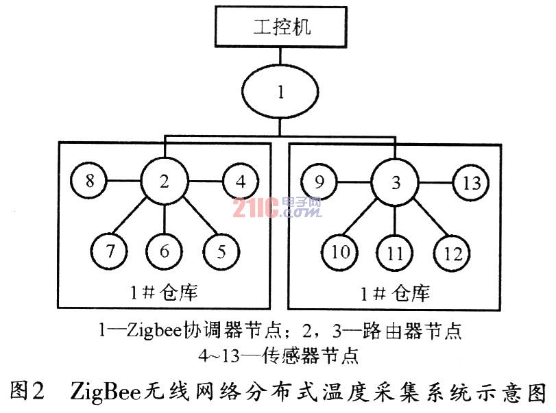
2 Principle of distributed temperature acquisition system This system consists of three types of nodes: ZigBee coordinator node, router node, and sensor node. Figure 2 is a schematic diagram of its composition, where the ZigBee coordinator is a distributed processing center, that is, a convergence node. Multiple sensor nodes are placed in different monitoring areas. Each sensor node will first transmit the data to the sink node, and then the sink node will pass the data to the host computer through the serial port for further processing and display to the user. The coordinator node can communicate with multiple sensor nodes, so that the system can monitor multiple areas at the same time, and when to detect which area is usually controlled by the user through the coordinator node. When there are many obstacles in the detected area or the coordinator node is far from the sensor node, the stability of the network can be enhanced by adding router nodes. When the user has no data request, the sensor node only performs low-power channel scanning.
3 Hardware design of the node
3.1 ZigBee wireless transceiver CC2430
The wireless module can be realized by wireless transceiver CC2430. CC2430 is an on-chip ZigBee product that truly conforms to the IEEE 802.15.4 standard by Chipcon of Norway. CC2430 is manufactured using Chipcon ’s latest SmaitRF03 technology and 0.18μm CMOS process, and is packaged in 7 × 7 mm QLP48. In addition to the RF transceiver, the chip also integrates an enhanced 8051 MCU, 32/64/128 KB of Flash memory, 8 KB of RAM, ADC, DMA, and watchdog. CC2430 works in the 2.4 GHz frequency band, uses low voltage (2.0-3.6 V) for power supply, and has low power consumption (27 mA when receiving data and 25 mA when sending data) and high sensitivity (-97 dBm ), The maximum output is 24dBm, and the maximum transmission rate is 250 kb / s. CC2430 has a small number of peripheral components. It uses an unbalanced antenna because connecting an unbalanced transformer can make the antenna perform better. The current consumption of the CC2430 wireless MCU during standby is only 0.2μA, and the current consumption when running under a 32 kHz crystal clock is less than 1 μA. Therefore, the life of a small battery can be as long as 10 years.
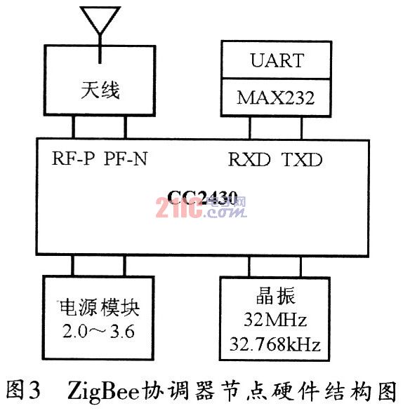
3.2 Hardware design of ZigBee coordinator node The hardware design of ZigBee coordinator node is shown in Figure 3. The node is composed of wireless transceiver CC2430, RF antenna RF, power module, crystal oscillator circuit and serial port circuit. The input / output of RF is high impedance and differential. The most suitable differential load for RF port is (115 + j180) Ω. When using an unbalanced antenna (such as a monopole antenna), in order to optimize performance, an unbalanced transformer should be used. The balun can be operated where low-cost individual inductors and capacitors are used. The power supply module is used for the power supply of the digital I / O of CC2430 and part of the analog I / O, and the power supply voltage is 2.0 to 3.6 V. CC2430 can be connected to the crystal oscillator circuit of two frequencies of 32 MHz and 32.768kHz at the same time to meet different requirements. The serial port circuit is used for the CC2430 to transfer the received data to the upper industrial control computer. Because the level of the upper industrial control computer and the CC2430 is inconsistent, a MAX232 level conversion circuit is needed.
3.3 Hardware design of the router node The main task of the router node is to route data from different areas from the sensor node to the coordinator node. Therefore, the circuit is relatively simple. The node consists of the wireless transceiver CC2430, radio frequency antenna RF, power module and Crystal oscillator circuit composition.
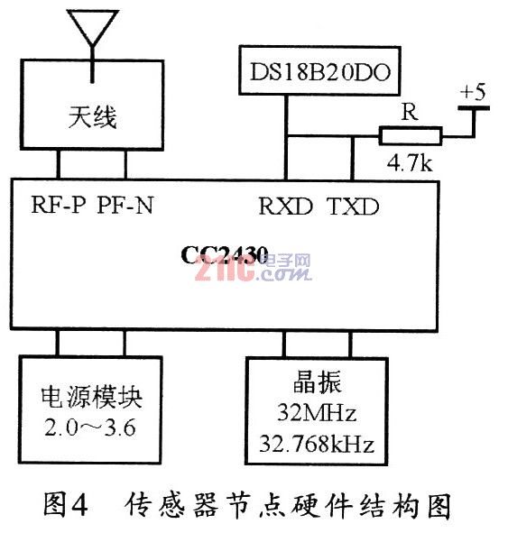
3.4 The hardware design of the sensor node The sensor node and hardware design are shown in Figure 4. The node consists of the wireless transceiver CC2430, radio frequency antenna RF, power module, crystal oscillator circuit and serial port circuit. DSl8820 and
The connection of CC2430 is very simple, only one interface cable is needed, and the interface is very convenient. Because each DSl8820 has a unique product serial number, it is allowed to connect dozens to hundreds of digital sensors on a single bus, and can easily form a multi-channel temperature measurement system. The DSl8820 has a 9-byte scratchpad. The two most significant bits (Most Significant Bit, MSB) and Least Significant Bit (LsB) can store the current temperature value in 16 bits. The two's complement form represents a 12-bit temperature reading, and the high bit is the sign bit of the temperature value. After the CC2430 sends out the temperature conversion command, the DSl8820 saves the measured temperature value in the MSB (high 8 bits) and LSB (low 8 bits 12 units) for the CC2430 to read.
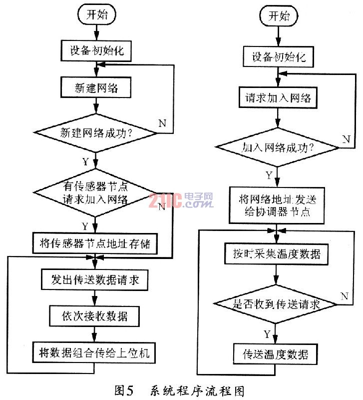
4 System software design The development environment used in this system is IAR7, and the protocol stack used is TI's Z-STACK. Because this system uses a tree structure, the ZigBee coordinator must know the network address of each sensor node. This requires that each sensor send the network address to the coordinator after joining the network. After the network address, the address table can be established and stored, so that when the user requests to collect temperature data, the data of each sensor is collected according to the address table. Figure 5 shows the program flow chart. The left side of the figure is the flow chart of the software design procedure of the coordinator node, and the right side is the flow chart of the software design procedure of the sensor node.
5 Conclusion The temperature acquisition system based on ZigBee technology can monitor multiple areas at the same time, and the development cost is low, the cost performance is high, the installation and maintenance are simple, and only a second installation can be used for long-term monitoring, so it has traditional temperature monitoring The advantages that the system does not have can better solve the problems of wiring and relocation in the traditional temperature monitoring system. Very suitable for environmental monitoring applications.
In electrical distribution, 100A Cut Out Fuse ( Composite Cut Drop Out Fuse or Composite Cut Out Fuse ) is a combination of a fuse and a switch, used in primary overhead feeder lines and taps to protect distribution transformers from current surges and overloads. However, Composite Polymer Cut Out Fuse is more lighter and also has efficient current transfer and higher interrupt capacities than Porcelain Cut Out Fuse.
Features
1. Efficient Current Transfer
2. Higher interrupt capacities
3. Fiberglass tube with UV resistant coating for the Fuse Tube
4. Superior quality of terminals made of tin plated copper alloys
5. High Quality stainless steel & hot dip galvanized fittings of the cutout`s assembly
6. High Quality HTV Silicone Rubber for the sheds/housing of polymer fuse cutout`s insulator
| MAIN DIMENSIONS AND STANDARD PARTICULARS | ||||||
| Type | RLF-11 | RLF-11 | RLF-12 | RLF-12 | RLF-16 | RLF-16 |
| Rated Voltage,KV | 24 | 24 | 15 | 15 | 36 | 36 |
| Rated Current,A | 100 | 200 | 100 | 200 | 100 | 200 |
| Breaking Current,A | 10000 | 12000 | 10000 | 12000 | 10000 | 12000 |
| Impulse Voltage,KV | 150 | 150 | 110 | 110 | 170 | 170 |
| Power-Frequence withstand Voltage,KV | 65 | 65 | 45 | 45 | 70 | 70 |
| Creepage Distance,MM | 540 | 540 | 245 | 245 | 720 | 720 |
| Weight,KG | 4.5 | 4.5 | 3.8 | 3.8 | 5 | 5 |
| Dimension,CM | 51x34x11.5 | 51x34x11.5 | 45x34x11.5 | 45x34x11.5 | 61x34x11.5 | 61x34x11.5 |


We warmly welcome friends both domestic and abroad to visit our company, if you have any questions, please contact with us directly.
Composite Cut Out Fuse
100A Cut Out Fuse,Composite Polymer Cut Out Fuse,Composite Cut Drop Out Fuse,Composite Cut Out Fuse
FUZHOU SINGREE IMP.& EXP.CO.,LTD. , https://www.cninsulators.com