Optimization design control method
This article refers to the address: http://
At present, the car is developing in the direction of automation and intelligence, realizing automatic line-seeking driving, self-implementing path change function, and driving fast on the basis of reliability, and getting more and more applications in actual production such as engineering and logistics. The design and development of the racing car model provides a solution and method for the realization of the vehicle hunt driving function. In this paper, the steering system of the racing vehicle model steering gear is optimized, and a fuzzy control steering steering control method is proposed.
Analysis of various control methods
At present, the automatic control methods adopted by people are roughly divided into three types: classic control, modern control and intelligent control.
Classical control is a commonly used control method, which is based on the transfer function. The general industrial production process belongs to the linear constant system, so it can be controlled by the classical control method. The classic control method is the pid control method [1-3]. The quality of its adjustment depends on the tuning of the various parameters of the pid controller. However, this control method can only solve the control problem of the linear steady system.
Modern control theory can solve the control problem of time-varying systems. In a time-varying system, the relationship between input quantity and output quantity changes with time. Therefore, modern control theory plays a big role in aerospace and military. Modern control methods are based on state equations.
Intelligent control [4-5] is an advanced stage of automatic control development. It is a highly integrated and integrated multi-discipline of artificial intelligence cybernetics, system theory and information theory. It is a new cross-cutting discipline. Intelligent control can independently drive intelligent machines to achieve their target control methods without human intervention. At present, intelligent control technologies, such as neuron network technology, fuzzy control technology, genetic algorithm optimization technology, expert control system, rule-based human-like intelligent control technology, etc. have entered engineering and practical.
Selection of control scheme
Classical control and modern control require the establishment of a precise mathematical model. However, in practical applications, some complex processes are difficult to obtain mathematical models or simply cannot obtain mathematical models. Intelligent control is a method of using human experience to control complex processes, and is constantly improving and developing. Fuzzy control [6-8] is one of the intelligent control methods. The intelligent racing car adopts fuzzy control and has the following advantages:
(1) There is no need to know the exact mathematical model of the controlled object in advance.
(2) The control rules are summarized in terms of human experience and are easy to grasp.
(3) It has strong robustness to the parameter changes of the controlled object.
(4) Control knowledge is expressed in the form of human language, which is conducive to human-computer dialogue and system knowledge processing, thus facilitating the flexibility and mobility of system processing.
Smart car design
Smart car front wheel steering design requirements
The smart car model is stable, fast and accurate, that is, the model car speed and driving route are required to be stable, the algorithm reaction and speed, the angle adjustment is fast, and the speed control and detection system are accurate. Therefore, the detection part must select reliable performance during the design process. Sensors with fast response speeds and intelligent algorithms to control vehicle travel [9-11].
Infrared sensor arrangement
For the road condition that the white background color is 60cm wide and the black line width is 2.5cm, the design uses 7 pairs of infrared sensors for road recognition. Each infrared sensor is 2.5cm apart and arranged in a horizontal line to ensure that only one photocell signal is black. The line is a stable target. In this way, the deflection angle can be divided into 7 levels according to the identification signal.
Steering gear control module
The hs-925 steering gear is used to control the steering of the front wheel of the smart car. It features large torque, good stability, simple control, easy interface with the digital system, and precise control angle.
Steering gear working principle
(1) The steering gear structure includes a reduction gear set, a position feedback potentiometer, a DC motor and a control circuit.
The working principle of the steering gear is shown in Figure 1. The reduction gear set is driven by the motor, and its output shaft drives a linear proportional potentiometer for position detection. The potentiometer linearly converts the rotation angle into voltage and feeds back to the control circuit board. The board compares it with the input control pulse signal to generate a correction pulse and drives the motor to rotate in the forward or reverse direction, so that the output position of the gear set matches the expected value, so as to achieve accurate positioning of the servo motor [12-13].
Figure 1 How the steering gear works
(2) Steering gear control
The control signal used in this system is a pulse signal with a period of 13ms. The direction of the servo can be changed by changing the pulse width. In addition, the pulse width and the rotation angle are linear [14-16]. The calculation formula is:
a=(l-1.5)×90° (1)
Where a is the corner of the steering gear, the unit is degrees; l is the pulse width, the unit is milliseconds. The correspondence between the corner and the pulse width is shown in Fig. 2.
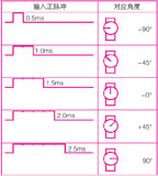
Figure 2 Control of the steering gear
In hardware implementation, a 16-bit pwm is used to drive the steering of the steering gear.
Design of fuzzy control scheme
The fuzzy controller has three functional modules: fuzzy, fuzzy inference, and clear, as shown in Figure 3.
Figure 3 Fuzzy controller
The establishment of the fuzzy subset and the membership function is shown in Figure 4.

Figure 4 infrared receiver tube coding
The fuzzy controller of the system adopts a conventional fuzzy controller, and the input quantity is the current position deviation e, and the output quantity is the servo control signal u.
The position deviation e is the deviation of the actual position returned by the photoelectric sensor from the central axis of the smart car. When e is zero, the smart car does not deviate from the path; when e is positive, the smart car deviates from the path to the left; when e is negative, the smart car deviates to the right. The deviation range e (the domain of the argument, the unit is cm) is [-9, 9], and the domain is discretized into a set of integers e={-9, -6, -3, 0, 3, 6, 9}. The quantization factor k = n / x = 1.0.
The value of the positional deviation e is obscured. Let the fuzzy subset e={nb, nm, ns, ze, ps, pm, pb}, where nb: [-9, -6], indicating left partial extra large; nm: [-9, -3], indicating The left is larger; ns:[-6,0], indicating that the left is smaller; ze:[-3,3], indicating the middle; ps:[0,6], indicating that the right is smaller; pm:[3 , 9], indicating that the right is larger; pb: [6, 9], indicating that the right is too large.
The membership function of e is a triangular function distribution, as shown in Figure 5.
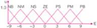
Figure 5 e membership function
Since the position deviation is positive or negative, the steering angle of the steering gear is also positive or negative, and the position fuzzy controller outputs a signal u that controls the deflection of the steering gear. When u is set to positive, the steering gear is deflected to the right. When u is negative, the steering gear is deflected to the left. The fuzzy subset of u is similar to the fuzzy subset of positional deviation e, ie u={nb, nm, ns, ze, Ps, pm, pb}. The size of u is also quantified into seven levels, the domain of which is u={-45, -30, -15, 0, 15, 30, 45}. The membership function of u is shown in Figure 6.
Control rule
Fuzzy rules reflect the relationship between input and output variables, and fuzzy control rules are the core of fuzzy control.
When the smart car is moving, the selection of the servo control signal u should be related to the magnitude and sign of the position deviation. When the absolute value of the position deviation e is large, the steering deflection should be controlled by a large absolute value control signal; and when the absolute value of the position deviation e is small, the steering deflection should be controlled with a small absolute value control signal. When the position deviation e is positive, that is, when the smart car deviates to the left, the control signal controls the steering gear to deflect to the right to reduce the position deviation; and when the position deviation e is negative, that is, the smart vehicle deviates to the right, the control signal is controlled. The steering gear is deflected to the left to reduce the positional deviation.
The fuzzy control rules are shown in Table 1.
Table 1 Fuzzy Control Rule Table

Fuzzy reasoning and clarity
Reasoning is the core of a fuzzy control system. Based on the fuzzy concept, fuzzy control information can be obtained through fuzzy inference rules and fuzzy logic inference rules, and can realize the anthropomorphic decision process. According to the fuzzy input quantity (deviation e) and the fuzzy control rule, the fuzzy reasoning solves the fuzzy relation equation and obtains the fuzzy output (deflection angle u).
Clarification is the process of converting a fuzzy set obtained after fuzzy inference into a digital value used as a control. The method of center of gravity can be used to make it clear. The center of gravity method refers to the method of taking the base variable corresponding to the center of gravity of the area enclosed by the axis of the basic variable as the clear value.
Steering gear control strategy and algorithm
The signal detected by the sensor is quantized to correspond to the calculation of the deflection angle of the steering gear. In addition, in order to avoid the overshoot from the straight into the bend, and the oscillation from the curve into the straight, the speed needs to be controlled in the program.
Quantitative process
The smart car samples the position by 7 light sensors. According to the layout of the sensor, it is numbered 1, 2, 3, 4, 5, 6, and 7 from left to right. Due to the dense distribution of the sensor, one or two sensors can detect the black line at the same time, so that 13 kinds of road conditions can be obtained. For the convenience of processing, the signal of the obtained sensor is quantized into [1, 2, 3, 4, 5, 6, 7, 8, 9, 10, 11, 12, 13].
Calculation of steering angle of steering gear
The final steering deflection angle is obtained by calculation. The specific calculation reasoning process is as follows:
(1) The corresponding deviation obtained by projecting the design position of the sensor onto the reference line is -9, -6, -3, 0, 3, 6, and 9 from left to right. Corresponding to 1, 3, 5, 7, 9, 11, 13 after the above quantization process. In this case, the quantified result can be represented by the zadeh notation to represent its fuzzy set on the domain e, such as: the position of 10 can be expressed as.
(2) Through fuzzy reasoning, the output of the quantized result (fuzzy amount) can be obtained, and the zadeh representation is expressed on the domain u, and the output result (fuzzy amount) corresponding to 10 can be expressed as.
(3) After clearing the center of gravity method to obtain the output result corresponding to each quantized result, the output result corresponding to 10 is 0.5×15+0.5×30=22.5.
(4) In order to make the racing car run smoothly on the straight road, the output results of the quantized values ​​5 to 9 are appropriately adjusted so that the output corresponding to the middle 6, 7, 8 is 0 degrees, and other corresponding adjustments make the angle change more average.
Speed ​​control
When the car is driving at a constant speed, entering the curve from the straight road may cause overshoot. If you enter the straight from the curve, there may be oscillation, so the speed must be adjusted. Specifically, the sensor is decelerated immediately when the sensor is detected to be out, and the original speed is restored when returning from the bias to the center position.
test results
By collecting the current road condition signal, the steering angle of the steering gear is controlled to realize the control of the tracking function of the trolley. The output of the front wheel steering angle of the smart car is controlled by the modulation pulse width of the steering input pwm signal. In the experiment, the pulse width is measured between 8316 and 9084 microseconds, and the rotation angle of the steering shaft is -45 degrees to +45 degrees. The steering mechanism transmits the steering angle to the front wheel. Neglecting the dynamic response process of the steering gear, when the steering gear is in steady state, there is a one-to-one mapping relationship between the pulse width and the direction angle of the front wheel. Therefore, the output of the fuzzy controller is to control the pulse width of the servo, ranging from 8316 to 9084 microseconds. When the output is set to 0 to 768 microseconds, the corresponding servo is rotated 45 degrees to the left or right. In this design, the direct change of the black line of the smart car is used as the deviation input, and the offset of the 8316 microsecond is added when setting the pulse width to the pwm module. The correspondence between the specific steering angle and pwm is shown in Table 2.
Table 2 Correspondence table between steering wheel angle and pwm

According to the fuzzy algorithm and the traditional pid algorithm introduced in this paper, two control programs are programmed for the smart car. The two control programs are downloaded to the mcu of the same smart car and run on the runway. Through multiple comparisons, the completed smart car is put on a specific runway for testing. As shown in Figure 7, Figure 8, Figure 9, and Figure 10, the experimental results show that the car can be well and quickly in the specified track. Driving inside. The steering controller based on fuzzy control can realize the steering control of the intelligent vehicle in the straight line, the curve with large radius of curvature, the curve with small radius of curvature, and the serpentine bend, and the steering stability is better.

Figure 7 The car is driving in a straight road
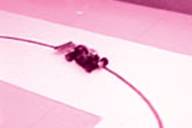
Figure 8 The car travels in a corner with a large radius of curvature

Figure 9 The car travels in a corner with a small radius of curvature

Figure 10 The car is driving in a serpentine curve
summary
The purpose of this paper is to use the fuzzy control algorithm to effectively control the steering system of the steering wheel of the smart car. The in-depth study and optimization of the parameters of the fuzzy controller are carried out, and the following conclusions are obtained:
(1) The membership function and fuzzy control rules are established. According to the inherent characteristics of the system, the fuzzy control rules are adjusted in real time in combination with expert experience. Compared with the method of changing the control rules by using the fuzzy control rule table, the proposed method can reflect the inherent characteristics of the system and is simpler to implement.
(2) According to the characteristics of the steering gear system, in order to improve the control performance of the system, a fuzzy controller is designed and applied to the steering gear control of the smart car system.
(3) Complete the design of the control system of the whole smart car steering gear, simulate the motion control strategy of the smart car by simulating the driving behavior, and control the steering angle of the smart car system by the conventional fuzzy controller, and carry out experiments and analysis.
Through the smart car experiment and competition, it is proved that the proposed scheme is advanced and effective.
About the Author
Wang Yongding (1963-) male professor, master tutor. School of Engineering, Shanghai Ocean University, the main research direction is power machinery engineering and logistics equipment automation technology.
references
[1] Tao Yonghua et al. New pid control and its application. Beijing: Mechanical Industry Press, 1998.
[2] Liu Yuanjin, Li Changyu, Zhang Mingxiong. pid tuning based on combination of rules and optimization methods [j]. Automatic Control Technology and Application, 1003-7241(2005)03-0019-03, 2005.
[3] liu jianchang. the system of automatic control [m].beijing, metallurgy industry press, 2001.
[4] Yi Jiyao, Hou Yuanbin. Intelligent Control Technology [m]. Beijing: Beijing University of Technology Press, 1999.
[5] Dong Jingxin et al. Editing Engineering Foundation. Beijing: Tsinghua University Press, 2003.
[6] zhu jing. the principle and application of fuzzy control[m]. china machine press(in chinese).
[7] hu shousong. the principle of automatic control [m].science press, 2001.
[8] Han Junfeng and other editors. Fuzzy Control Technology. Chongqing: Chongqing University Press, 2003.
[9] Zhuo Qing, Huang Kaisheng, Shao Beibei. Learning to be a smart car [m]. Beijing: Beijing Aerospace Publishing House, 2007: 158-160.
[10] Huang Kaisheng, Jin Huamin, Jiang Dinan. Analysis of Korean smart model car technology program. Electronic Products World, 2006: 150-152.
[11] Wang Wei. Detection of driving distance and speed of wheeled smart car [j]. Sensor Technology, 2005: 76-78.
[12] Li Tiecai, Du Kunmei, ed. Motor Control Technology. Harbin: Harbin Institute of Technology Press, 2000.
[13] Editor-in-Chief Wang Jianguang. Motor Control System. Beijing: Mechanical Industry Press, 1994.
[14] Yu Haisheng, Pan Songfeng, Yu Peiren, Wu Herong. Microcomputer Control Technology [m]. Tsinghua University Press, 2004.
[15] Wang Xiaoming. Single-chip control of electric motor [m]. Beijing: Beijing University of Aeronautics and Astronautics Press, 2002.
[16] Lu Pingbao. Research and application of intelligent digital-analog hybrid pwm speed governor for DC motor. Master's thesis of Qingdao Institute of Chemical Technology [d], 2002.
Stainless Steel Coffee Urn,Catering Coffee Urn,50 Cup Coffee Urn,Mechanical Coffee Urn
FOSHAN FORTUNE ELECTRICAL APPLIANCE CO.,LTD , https://www.coffelady.com