This article will introduce a new method that has proven to be effective in performing these measurements. It is a relatively low cost, simple setup time measurement method. This approach establishes accuracy and precision in the relative speed of the waveform generator and sample-and-hold circuit.
Stepping Inputs for the Device Under Test <br> In this paper, settling time is the time it takes for an instrumented device (DUT) to enter and maintain within a specified error range (final value symmetry) using an ideal step input. The ideal step input is easy to generate in the simulation, but there are no instruments in the lab that produce the ideal step waveform. Even under ideal conditions, the output of overdamped and highly damped instruments may require some RC time constants to monotonically stabilize within 0.1% of the final value range.
For some underdamped systems, the step waveform will exceed the final value and ringing may occur. In fact, even high damping systems can be underdamped. In general, the faster the step waveform falls, the more overshoot and ringing. This non-ideal condition then propagates to the measured output waveform of the device under test. Fortunately, the computer logs the input and output data, and the output is normalized by arranging the two types of data and subtracting the input with the output (the device under test uses the in-phase unity gain configuration).
Flat-bottom pulse generator <br> When the waveform generator falling edge is used as the input to the device under test, a flat-bottom pulse generator (FBPG) can be used to flatten the low-voltage level of the generated signal. The flat-bottom pulse generator clamps the voltage drop to ground at the expense of a larger overshoot. This allows the test engineer to adjust the balance of the test program to achieve control of certain programs. Again, we can use a flat-top pulse generator to level the high voltage level.
Figure 1 shows two high-speed Zener diodes placed back to back, each with a separate, adjustable power supply. The general rule is to start the device in the following order: adjust Rsupply, get D1/D2 to connect 5V, then adjust the Vgenerator output voltage to swing between 2V high and -5V low. This will bias the output at 2Vpp high voltage level and 0V low voltage level. When Vgenerator is high, D2 is off and D1 is on. During this time, the output voltage becomes a function of the D1 forward voltage (Vsupply) and is also a function of the amount of current flowing through Rsupply and D1. When the input is low, D1 is off and D2 is on. During this time, the output voltage swings to ground and its slew rate is proportional to the amount of current flowing into the corresponding resistor R3. The transient response is related to diode capacitance, reverse recovery time, and forward recovery voltage.
Figure 1 Flat-bottom pulse generator (FBPG)
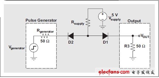
Due to the nonlinear nature of the diode, a rigorous equation is used to calculate the DC level and the flat bottom pulse generator transient response. As an alternative, these equations can also be simulated in software such as TINA-TITM from Texas Instruments. Assuming the pulse generator is very fast, the fall time and overshoot of the output waveform is related to the speed and recovery time of the diode, as well as the parasitic capacitance and the inductance of the printed circuit board (PCB) on which the flat-bottomed pulse generator is mounted. In other words, designers should choose the fastest, most robust diodes and follow the principles of good PCB layout when using flat-bottom pulse generators for high-speed waveform generation.
Establishing a sample-and-hold method for time measurement <br> For the example presented here, we chose to use TI's OPA615 (see Figure 2) to implement the sample-and-hold (S/H) function of establishing time measurements because: it has Wideband Operational Transconductance Amplifier (OTA) optimized for low input bias currents; it also features fast, accurate sampled OTA (SOTA), which acts as both a comparator and a buffer. When the hold control pin is high, the analog input (VIN) is sampled on the capacitor (CHOLD) via SOTA. When the hold control pin goes low, the CHOLD voltage is held and reflected at the output (VOUT). During sampling, the CHOLD voltage is adjusted to the input real-time voltage level. If the difference between the input and CHOLD is large and the sampling time is only a few nanoseconds, a high slew rate is required. During hold, the CHOLD voltage is always charged/discharged due to its leakage current and the bias current required by the OTA. The current feedback loop ensures that the SOTA slew rate is sufficient to capture the correct voltage level of VIN.
Figure 2 sample and hold ( S / H ) circuit

Figure 3 shows an example of a 100kHz sine wave input S/H output. We can use a waveform generator to generate the input step function of the device under test and synchronize the S/H signal with the step function. The S/H circuit can be used to capture various points on the output waveform of the device under test. If there is a marker output that is synchronized with the output, any arbitrary waveform generator is active, resulting in a very suitable hold control signal. An example test uses a Tektronix AWG610 with a 2.6 Gbps sampling time and a minimum mark step of 100 ps, ​​making it suitable for most high speed op amp setup time measurements.
Figure 3 Example 1MHz S/H output of a 100kHz sine wave
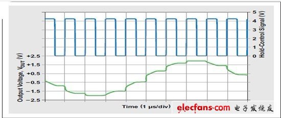
Figure 4 depicts how an S/H circuit can be used to capture various points on the curve, while the S/H circuit uses the marker as a hold control signal. Designers can capture successive points on the curve by moving the marker position. After all points have been recorded, the S/H curve can be plotted for analysis. It is a very simple method to program the waveform generator using software such as MATLAB® or LabVIEWTM to change the markup and record the results. When the flag is set to position 1, the S/H circuit tracks the VIN voltage level when the flag is high and holds it when the flag is low. At position 1, the output remains at 1V. At position 2, the output remains at 0.2V.
Figure 4 Example of tag synchronization for AWG610 output
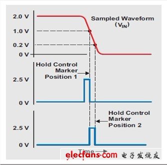
Figure 5 shows a test setup for establishing time measurements that implements S/H functionality using AWG 610 and OPA 615. All signal lines are 50Ω. The waveform generator output is used as a test signal and uses two S/H circuits: one to measure the input of the device under test (OPA656) and the other to measure the output of the device under test. A digital multimeter (DMM) is used to record individual hold values.
DMX512 Digital LED Strip is a programmable led strip, be controlled by the international standard DMX512 protocol, which is addressable and programmable
by using the external drive chip DMX512.Compatible with and extend DMX512 (1990) signal protocol, the control mode is differential parallel,
built-in 485 decoding module, strong anti-interference ability, low-voltage DC24V,very safer for users.
Supports the operation mode of first installing and writing code later, and can realize any animation effect of the product through controller programming.
Suitable for large engineering projects.
DMX512 Digital LED Strip
High CRI LED Strip,Outdoor LED Strip Light,DMX RGB LED Strip,DMX512 Digital LED Strip
SHEN ZHEN SEL LIGHTING CO.,LTD , https://www.sellighting.com