The ignition system of the automobile engine includes hundreds of electrical and mechanical parts, and the production line is widely distributed. Therefore, the distributed indirect monitoring method is widely used in the monitoring and fault diagnosis system of the ignition system. The engine ignition performance tester analyzes the performance of the distributor and igniter by measuring the closed angle and the firing angle of the engine.
This article refers to the address: http://
Relationship between closed angle, fire angle and ignition advance angle
Closed angle
Taking a gasoline engine four-stroke engine as an example, the piston reciprocates four single passes to complete one duty cycle, and the four strokes include intake, compression, work, and exhaust strokes. In one working cycle, the engine camshaft rotates 360° a week.
In the ignition system, the current of the primary winding of the ignition coil is from the cut-off to the on-off to the cut-off period, and the cam angle occupied by each cylinder of the multi-cylinder engine is called the closed angle. In a complete duty cycle, the primary current experiences a total of four cycles from turn-off to turn-on and turn-off, producing four ignition pulses, one for each of the four cylinders. As shown in Figure 1, the four-stroke 4-cylinder engine has a duty cycle T of
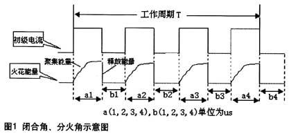
T = (a1 + a2 + a3 + a4 + b1 + b2 + b3 + b4);
Where ai(i=1,2,3,4) is the time at which the primary current is turned on for the ith time in the duty cycle T, and bi(i=1, 2, 3, 4) is the primary current during the duty cycle T The time of the i-th deadline.
The closing angle α1 of the first cylinder is α1=a1×360°/T;
The closing angle α2 of the second cylinder is α2=a2×360°/T;
The third and fourth cylinders are similar.
If the closing angle is small, the closing time is short, and the primary current is not increased by the required value, the ignition energy is insufficient. If the closing angle is too large, it means that the contact gap is small, which will cause the contact to arc discharge, but weaken the ignition energy, which is not conducive to normal ignition, and the contact closing time is too long, the primary current Continue to energize after increasing to the maximum value and also cause the ignition coil to heat up. When the closing angle is the same, the high speed takes a short time and the low speed takes a long time. The closing angle varies with the speed of rotation is the best case. Generally, the closing angle of the 8-cylinder machine is 29° to 32°, the 6-cylinder machine is 38° to 42°, the 4-cylinder machine is 43° to 47°, and the 3-cylinder machine is 63° to 67°.
Fire angle
Observing the uniformity of the fire angle is one of the key aspects of the ignition test of the automobile engine. Here, the 1-cylinder fire angle β1 is βl=(al+b1)×360°/T;
The 2-cylinder fire angle β2 is β2=(a2+b2)×360°/T;
The third and fourth cylinders are similar.
Ignition advance angle
The gasoline engine draws in the mixture in the cylinder and takes a certain amount of time to burn. In order for the piston to fully burn in order to reach the top dead center, to achieve maximum power, the spark plug should be fired before the piston reaches the top dead center. The angle at which the crankshaft turns from the start of ignition to the time when the piston reaches top dead center is the ignition advance angle. If the ignition is too early, there will be knocking when accelerating, and a sound similar to a metal tap will be emitted. The piston will be blocked upwards, the efficiency will be reduced, and the wear will be intensified. If the ignition is too late and the gas work efficiency is low, the engine is not easy to start, the speed is slow, and the exhaust pipe is released and the engine is overheated. Therefore, ignition too early or too late will affect the increase in speed.
The biggest factor affecting the ignition advance angle is the speed. As the speed increases, the time to turn the same angle becomes shorter. Therefore, the optimum ignition advance angle can be adjusted according to the engine closing angle and the firing angle. The purpose of the adjustment is to make the maximum expansion of the gas in various conditions in the piston work power reduction stroke, achieving the highest efficiency, minimum vibration, and lowest temperature rise. Theoretically, the minimum ignition advance angle is 0°, but in order to prevent ignition of the intake air during the intake stroke, it is often set to 5° or more, generally not more than 60°.
Circuit design
The ignition performance tester includes a power module, a measurement and control module, a display module, etc., and its circuit block diagram is shown in FIG. 2 . 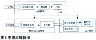
The power module converts 220V AC power to 5V DC for other modules. After the measurement and control module collects and limits the ignition signal, it inputs the single-chip microcomputer 89C52 to measure and calculate the closed angle and the fire angle. The obtained angle value is sent to the display module, and the angle value is sequentially displayed according to the firing order of the cylinder.
Measurement and control module design
The functions of the measurement and control module are mainly realized by the pre-processing circuit and the single-chip microcomputer, as shown in Figure 3. The pre-processing circuit limits and shapes the input ignition signal to suppress the interference signal, especially suppressing over-voltage or negative voltage that may be generated. Limiting and shaping are mainly done by the operational amplifier integrated chip LM324 combined with the on-off characteristics of the diode. The square wave signal output by the LM324 is inverted by the inverter 74LS14, and the two signals are inverted with each other, wherein the inverted signal of the ignition signal is connected to the pins P1.0 and INT0 of the 89C52, and the other channel is connected to the P1.1. And INT1.
The 89C52 microcontroller is the core chip for measurement and control modules. The ignition cycle signal frequency during the test is low, so the logic of the signal controls the operation of the counter, the signal input terminal is high when counting, and when it is low, the counting is stopped. The software sets the control bits TR0 and GATE to 1 and selects the counter 0 mode to mode 1. The TH0+TL0 count depends on the signal of the INT0 pin. When INT0 changes from 0 to 1, it starts counting. INT0 is 1 When it changes to 0, it stops counting. During the counting process, the level of the P1.0 signal of the I/O port is tested by the query mode. When the level is high, the counter automatically counts; when the test reaches the low level, it indicates that the counting is finished, and the MCU can take the count value and calculate the counting result. Thus, the high pulse width of the INT0 signal can be counted by the counter 0. This design method effectively guarantees the speed and accuracy of counting. Similarly, the low pulse width of the INT1 signal can be counted by the counter 1. The count values ​​of the counters 0 and 1 are calculated by software, and the closed angle and the fire angle of the ignition are obtained, and the data serial output corresponding to the angle value is sent to the LED display module for display.
In addition, P1.0 and P1.1 are used to query the status of the count. If the status of the P1.0 port is "0", it indicates that the counter 0 is completed, and the counter 0 value can be obtained. P1.1 and counter 1 work the same way. Since P1.0 and P1.1 test the inverted signal, two half-wave count values ​​of one periodic signal can be obtained. After processing, the corresponding angle value can be calculated. There is no delay error or an interrupt error in the interrupt mode. 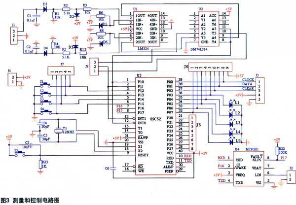
The keyboard input man-machine interfaces S1 and S2 are designed in the circuit. S1 is the input function key and S2 is the system start key. The S1 has two functions: the car cylinder number selection function and the cylinder number reset function. The button S1 is connected to the P1.2 of the 89C52, and the number of cylinders is incremented by one each time. After selecting the number of cylinders, press the test button S2 connected to P1.3 to start the test. In order to reduce the button design, in any state, as long as you press and hold the S1 button, you can immediately return to the initial state, and the cylinder number selection step reselects the cylinder. number.
Display module design
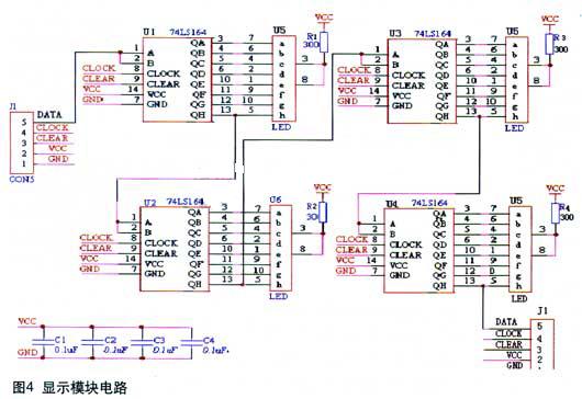
In the actual measurement, since the angle value is in degrees, it will not exceed 100 digits, and it is accurate to tenth position. Therefore, the four LEDs can display the ignition angle of one cylinder, and the cascade can display multiple channels. The ignition angle of the cylinder. This system adopts the serial working mode and uses 4 LED digital tubes for display.
The 89C52's data is serially input to the display module. Both the shift clock pulse CLOCK and the clear signal CLEAR are controlled by software. The TTL one-way 8-bit shift register is used in the display module to realize serial input parallel output and directly drive the common cathode eight-segment LED digital tube. In addition, use the three I/O pins of the 89C52 to connect the LEDs L4 to L6 for status display during operation. When L4 is lit, it indicates that the closed angle angle is currently being displayed. When L5 is lit, it indicates that the fire angle angle is currently being displayed. When the number of cylinders tested is greater than 4 cylinders, L6 will illuminate as a reminder, as shown in Figure 4.
During initialization, press S1 and LED to display the number of cylinders to be tested. Press S2 to enter the working state. Take the 4-cylinder engine as an example. In each round of display, the 4-way LED display module displays the angle of the 4-cylinder closed angle at the same time, while L4 lights up, and changes to L5 after 3 seconds. Lights up, and the LED panel shows the angle of the fire angle. In order to improve the utilization rate of the seven-segment digital tube, this design adopts the method of turning the page value of the angle value for the engine with a large number of cylinders. For example, an 8-cylinder engine can still use only 4 LED display modules. The first wheel only shows the angle value of the first 4 cylinders, the second wheel shows the angle value of the rear 4 cylinders. When the rear 4 cylinder angle is displayed, L6 Will light up as a reminder.
software design
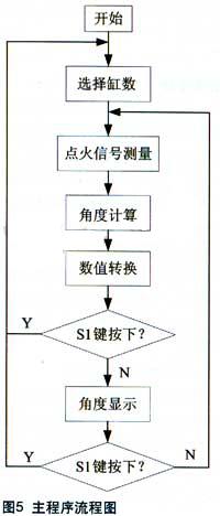
After a certain pre-processing, the ignition signal is transmitted to the 89C52 MCU to complete the measurement, calculation and corresponding display. The software flow chart of the main program is shown in Figure 5. The software design mainly includes modules such as cylinder number selection, counter counting measurement, interrupt service, angle calculation and display.
Cylinder number selection module programming
The number of cylinder selection buttons S1 is provided on the panel of the tester, and the number of cylinders is incremented by one each time. After selecting the number of cylinders, press the button S2 to start the test. In addition, there are multiple queries for the button S2 in the program. If you want to re-select the number of cylinders during the working process of the tester, you can press S2 at any time without releasing it. If the time is longer, it will be queried and the program will re-enter. The number of cylinders is selected.
Counter counting and interrupt service program design
When the speed exceeds the calibration range of the tester, a counter 0 or 1 overflow interrupt will be generated. At this time, the LED displays "E", meaning "ERROR". You only need to adjust the speed in real time to re-enter the counting program and start measuring.
Angle display programming
After calculating the angle value of the closed angle or the fire angle, the angle value of the binary form is converted into a BCD code temporarily stored in the accumulator by the decoding program, and the accumulator serially transmits the angle data to the 74LS164 and then to the eight segments. The digital tube displays the decimal angle value of the current BCD code.
Conclusion
In this paper, the hardware and software development of the 89C52-based automotive ignition performance tester is completed under the SUPERIMAGE-3000 development environment. The experimental data and the loading test results are stable and reliable, and the accuracy is up to standard. It can be effectively used as the analysis of engine distributor and igniter quality. The index is important for adjusting the efficient ignition timing and ignition advance angle.
Simplex Patch Cord is a length of optical cable with connectors fixed on two ends to realize the optical path active connection.A series of simplex fiber patch cable is single mode 9/125um and multimode 50/125um, 62.5/125um,& 10Gb Om3 Fiber Patch Cord with different jacket types,such as Riser Jacket (OFNR), Plenum Jacket (OFNP), PVC Jacket, Low Smoke Zero Halogens (LSZH). Simplex Fiber Optic Patch Cord can be made to any length to fit FTTH projects.The simplex patch cord series comes with a comprehensive collection of lengths and connectors to fulfill your demand for the deployment
Simplex Patch Cord
Simplex Patch Cord,Simplex Patch Cables,Simplex Optic Patch Cord,Fiber Optic Patch Cables
Foclink Co., Ltd , http://www.scfiberpigtail.com