In order to solve the numerous control and data exchange problems in modern vehicles, Bosch developed a CAN (Controller Area Network) fieldbus communication structure. The CAN bus hardware connection is simple, with good reliability, real-time performance and price/performance ratio. CAN The bus can meet the needs of modern automation communication, and has become the most important part of the industrial data bus communication field.
This article refers to the address: http://
Its main features are: 1CAN bus is a multi-master bus, each node can actively send information to other nodes on the network at any time, regardless of master-slave, flexible communication; 2CAN bus uses a unique non-destructive bus arbitration technology, The node with higher priority preferentially transmits data, which can meet the real-time requirement; 3CAN bus has the function of point-to-point, point-to-multipoint and global broadcast data transmission; 4 CAN bus has a maximum of 8 valid bytes per frame, and has CRC and Other verification measures, data error rate is extremely low, in case of a serious error in a node, it can be automatically disconnected from the bus, other operations on the bus are not affected; 5CAN bus has only two wires, when the system is expanded, the new node can be directly It can be hung on the bus, so there are few wires, the system is easy to expand, and the modification is flexible. The 6CAN bus has a fast transmission speed. When the transmission distance is less than 40m, the maximum transmission rate can reach 1Mb/s. It is because the CAN bus has these other The incomparable advantages of communication methods make it an ideal bus for electric vehicle control systems.
1 The demand for communication networks in electric vehicles
Due to the limited capacity of energy storage equipment, electric vehicles are very strict in energy management during operation. Efficiency is an important indicator to measure the performance of electric vehicle systems. The national 863 “fifteen†electric vehicle major special requirements motor system rated efficiency is 85%. The rated efficiency of the controller is 95%. The dynamic information of the electronic control system of the electric vehicle must be real-time. Each subsystem needs to share the public data of the vehicle in real time, such as motor speed, wheel shift, accelerator pedal position and brake pedal position. However, the control cycles of different control units are different, the data conversion speed and the priority of each control command are different. Therefore, a data exchange network with priority competition mode is needed, and it has a very high communication rate. In addition, as a kind of load Human transportation, electric vehicles must have better comfort, the vehicle communication system must have strong fault tolerance and fast processing capabilities.
At present, the development of electric vehicles has been highly valued by various countries. Electric vehicles have become the mainstream of future automobile development. There are many electrical components in electric vehicles, and there are many data that need to be transmitted and shared in real time. How to improve the real-time and reliable communication of electric vehicles Sexual and emergency processing capabilities become the difficulty of electric vehicle communication. We use TMS320LF2407 DS as the main processor of electric vehicle communication system, using DSP's good fast processing capability to improve data processing speed, thus improving the real-time communication; using DSP The embedded CAN bus module acts as the controller of the CAN, which reduces the complexity of the hardware circuit and improves the reliability of the communication. The software design emergency time shields the secondary factors to improve the emergency handling capability of the electric vehicle.
2 control plan
The electric vehicle assembly control adopts advanced fuzzy control, and the controller used is also the TMS320LF2407 type DSP. The obtained brake signal, acceleration signal and feedback back speed signal are blurred to obtain the desired speed signal, and will be obtained. The speed value is transmitted to the control mechanism of the motor through the CAN bus to control the motor to meet the driver's driving intention. At the same time, the lighting system and the screen display system are managed. The screen display system displays the running status of the electric vehicle in real time. The specific control scheme is shown in the figure. 1 is shown.
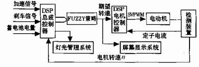
Figure 1 Block diagram of electric vehicle control system
3 electric vehicle CAN bus communication scheme
Electric vehicle control requires good communication coordination and operational reliability. A good communication system is the key to the reliable operation of electric vehicles. The CAN bus structure is a serial communication network that effectively supports distributed control or real-time control. Figure 2 A typical electric car CAN bus structure diagram, including the main motor controller of the vehicle power part, battery management system, electric vehicle screen display system and other equipment, these subsystems through CAN for data communication and command transmission. Each node device can independently complete the operation of its own system without leaving the CAN bus, thus meeting the needs of vehicle operation safety. At the same time, the CAN bus will not collapse due to the detachment of a certain device.

Figure 2 Electric vehicle CAN bus structure diagram
4 CAN bus module
The CAN bus module is a 16-bit peripheral of the DSP and is a complete CAN controller. In addition to the basic functions of the CAN bus, there are some unique functions, such as: the object has six mailboxes, and the data length is 0~ 8 bytes, two of which receive mailboxes (0, 1), two send mailboxes (4, 5), two can be configured to receive or send mailboxes (3, 4); automatic reply remote request function; programmable CAN bus wake-up function; self-test mode function, etc. Access to the CAN bus is divided into control/status register access and mailbox RAM access. The memory space allocation diagram of the CAN bus control module is shown in Figure 3.
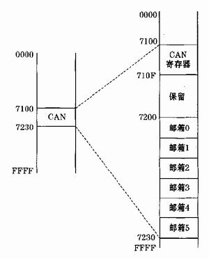
Figure 3 CAN bus memory space allocation
There are two kinds of information frames sent by the CAN controller, one is to send data frames, the other is to send remote frames. The sending mailbox has mailbox 4 and mailbox 5 and the mailbox 2 and mailbox configured to send mode. When sending data frames After the data is written to the data area of ​​the sending mailbox, if the corresponding sending request bit is enabled, the data frame is sent to the CAN bus. The data area of ​​the data frame can be set to 1-8 bytes by software. Data frame The format is shown in Figure 4.
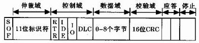
Figure 4 CAN bus data frame
The receiving mailbox of the CAN bus controller has mailbox 0 and mailbox 1 and mailbox 2 and mailbox configured to receive mode. When receiving the information, the CAN controller first needs to receive the identifier of the receiving information and the corresponding receiving mailbox identifier. In comparison, only the information with the same identifier can be received. The receive register of the CAN bus controller allows the receiving mailbox to ignore more bits to receive the information. However, if the receive mask enable bit (AME) is 0, then local The receive mask register will be invalid. Only the mailbox 2 and mailbox 3 configured as the send mode can receive the auto answer remote frame. When the mailbox receives the remote frame, the receiving node will automatically send a data frame as a response.
5 interface circuit design
Since the DSP itself has a CAN bus module, there is no need for a dedicated CAN controller. The DSP itself does not have a CAN transceiver. It requires an external CAN transceiver 82C250 and an optical isolator 6N137. If the distance is short, optical isolation is not required. The connection between DSP and opto-isolator and CAN transceiver hardware is shown in Figure 5.
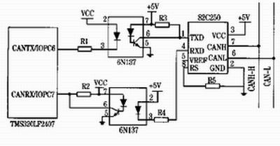
Figure 5 DSP and CAN bus hardware connection diagram
6 Software implementation of CAN communication for electric vehicle assembly controller
The electric vehicle assembly controller is the heart of the electric vehicle. It needs frequent receiving and transmitting data to control and detect the electric vehicle in real time. The sending information is in the inquiry mode, and the receiving information is interrupted. By setting different priorities of different events. To determine the order in which information is received and sent, and to increase emergency procedures to improve the controller's ability to handle emergencies, ensuring vehicle and personal safety. Emergency procedures are used when an emergency occurs, such as performing device damage, sudden braking and Sharp turn, etc., by temporarily shielding low priority events, such as battery power detection, LCD display system, etc., so that the controller has enough time to handle emergency events to improve the controller's real-time control capability and emergency processing capability. Controller software flow The figure is shown in Figure 6.

Figure 6 controller software flow chart
7 Conclusion
At present, fieldbus is rapidly developing in the field of automation. As a very influential field bus, CAN bus adopts many new technologies and designs, making CAN bus one of the most promising fieldbuses. CAN bus High real-time, high reliability and high flexibility have been used in industrial automation control. This paper uses DSP controller as the microprocessor of CAN bus, which utilizes DSP's strong data processing capability and CAN bus. The high transmission rate and high reliability feature solutions for complex communication systems in electric vehicles. Experiments show that the system not only solves the real-time requirements of electric vehicle communication, but also improves reliability and stability.
Travel Charger Adapter is convenience for these people who always travel in many countries. Desktop Power Adapter have normal DC connector for your need, and wall power adapter have mutil plug, like US/UK/AU/EU etc. We also can produce the item according to your specific requirement. The material of this product is PC+ABS. All condition of our product is 100% brand new.
Our products built with input/output overvoltage protection, input/output overcurrent protection, over temperature protection, over power protection and short circuit protection. You can send more details of this product, so that we can offer best service to you!
Travel Charger Adapter
Travel Charger Adapter,Portable Travel Charger Adapter,Mini Travel Charger Adapter,Travel Charger Supply
Shenzhen Waweis Technology Co., Ltd. , http://www.waweis.com