Author: Roger Alm
Light-emitting diode ( LED ) lighting opens up new horizons for unconventional, comfortable and customizable. These design opportunities are rapidly increasing the level of application and speed of LEDs in the car. There are several methods and design techniques to choose from when using LEDs in the car, in front of the car, and in the rear of the car.
For automotive LEDs, the relative anti-vibration, long life, high energy efficiency and fine control of the light source are key factors. Compared to incandescent bulbs, LEDs are not sensitive to mechanical shock, but require a drive circuit. In general, automotive electrical power systems use a lead-acid battery that is charged by the engine through a mechanically driven alternator/regulator. Such a system is suitable for old-fashioned incandescent bulbs, but not for LEDs. In order to achieve the best performance of the LED, a precise constant current source is required.
In order to properly drive the LED, the current needs to be controlled regardless of the voltage. The light output is basically dependent on the current and not the voltage. In theory, each electron is converted into a photon, and a fixed proportion of the photons that escape the LED become the light we see.
If the voltage is constant, only one resistor is needed to achieve a low quality solution. It should be noted that when the LED and the resistor are simply connected in series, the LED itself is self-regulating to some extent. If the temperature rises, the efficiency and brightness of the LED decrease, and the forward voltage drop decreases simultaneously. The reduced forward voltage drop in turn causes an increase in current,
This somewhat compensates for the decrease in brightness due to temperature rise. As long as the battery voltage is constant, the series resistor scheme is sufficient for computer and instrumentation applications. However, the automotive industry mandates that equipment be able to withstand battery variations between 8V and 18V and tolerate peaks of 80V. In addition, high-brightness LEDs generate a lot of heat on the resistors. This makes thermal design more difficult.
A better but not the best alternative is to use a dc-dc voltage converter to generate a suitable regulated voltage and then combine this with a resistor. This solution works if you already have a dc-dc converter that powers your computer or other electronic device. In addition, this method may be the most common method of driving LEDs. However, it is a better solution to drive the LED with a voltage-independent constant current regulator. Energy consumption and energy conversion are two basic types of current regulators, respectively.
A linear buck constant current regulator is an example of an energy consuming constant current regulator. For a given current, the energy consumption represented by the voltage drop across the current regulator is consumed. The other case is an energy conversion current regulator that attempts to store the energy difference between different levels.
The equation used to describe this energy conversion is one of the basic laws of thermodynamics:
·Input power = output power
· Given with W=V·I (given), replace W in the formula:
·Vin·Iin=Vout·Iout+(100-X% efficiency) W fever (fever)
If the forward voltage of the LED is taken as Vout and the required current is taken as Iout, a general equation describing the LED driver will be obtained.
Energy-consuming LED driver
It is relatively simple to build a linear constant current device with discrete components. Figure 1 is a constant current device built with discrete components. D1 should be a Zener diode or voltage reference. The current is determined by the equation ILED=VD1/RSET. D2 provides simple temperature compensation for the transistor base diode.
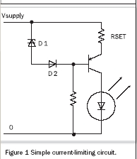
Although this circuit is simple, like all energy-consuming LED drivers, there are energy consumption and heat generation problems caused by resistors. As the brightness of the LED increases, the heat will become more and more serious. The brighter the LED points, the more energy is wasted.
This type of current stabilization can be used when the current is small and the sum of the forward voltages of the LEDs is slightly lower than the supply voltage. This constant current method is used by several LED driver IC manufacturers. However, this method is not recommended when driving high-brightness LEDs.
Saved LED driver
In many cases, switching current regulators provide a better electronic solution. The switching current regulator controls the on/off of a series load, which is hence the name. The RLC (slot circuit) circuit is charged in one cycle. In the next cycle, the stored energy is used to drive the load or to increase the voltage level of the energy center that drives the load. This energy arrangement generally achieves efficiencies greater than 80%, and in most cases can reach more than 90%. Therefore, the switching current regulator can be used to boost the voltage, lower the voltage, or even reverse the voltage. Linear constant currents do not have these capabilities. 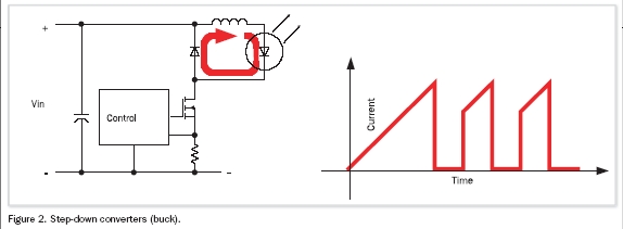
Job Description: The voltage difference between the input voltage and the LED voltage to charge the coil L. When energy is accumulated in the coil, the voltage above it will drop and the current will increase. When the current reaches a specified value, the control circuit will sequentially turn off the transistor. Then, within a certain off time, some of the energy in the coil will power the LED. This causes an overlapping current to flow through the LED. The switching current regulator circuit controls the peak current. This value can be set by programming the current regulator IC or an external device. The current also depends on the choice of sense resistor at the drain terminal of the NFET switch.
In a buck constant current application, the current flowing through the LED is continuous but overlapping. The energy consumption of the entire circuit is not continuous (Figure 2). It can cause problems on the power input side and easily cause noise through the power line.
Boost regulator
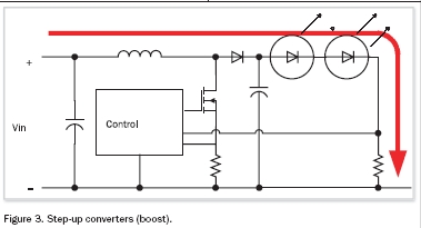
If the supply voltage is lower than the sum of the forward voltages of all series connected LEDs, the boosting constant current is used. Since the boosting current regulator has to control the increased voltage in addition to the current, such a current regulator is more complicated.
This boosting constant current regulator cannot handle the case where the supply voltage is higher than the sum of the forward voltages of all series connected LEDs. When this happens, the current will increase drastically without control, as shown in Figure 3.
This LED driver will also generate a ripple current that flows through the LED. Since the current flowing through the LED is relatively large, it is difficult to be filtered out. In principle, a simple boosting current regulator produces more noise on the current output to the LED. Therefore, when wiring the PCB, make the connection between the driver and the LED as short as possible.
SEPIC constant current regulator
The SEPIC current regulator is a single-ended primary inductor converter. This constant current regulator can be used both as a boost and as a step-down. However, the capacitive reactance between the coils is one of its drawbacks. This capacitor must handle the full energy converted to current and voltage for the LED.
This type of constant current device comes in handy when you basically need a step-down constant current regulator and there may be overvoltage on the power line.
Boost/buck constant current regulator
The safest and safest solution for a good boost LED driver is to combine a boost current regulator and a buck constant current regulator in a cascaded manner. This architecture minimizes the work required for optimization. A boosting current regulator is more suitable for supplying power to several parallel buck constant current regulators. Lighting Engineer Community bP!x5Dv L2g
For noise reduction, this approach is still a significant solution. It combines the excellent voltage output of the boosting current regulator with the excellent current output of the step-down constant current device.
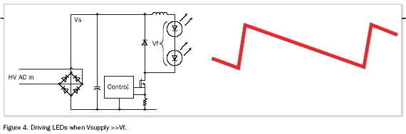
Driving LEDs by high voltage
When the power supply voltage is high and the forward voltage drop (Vf) of the LED is 10 to 20 times lower, there is a problem caused by a very short charging time for the coils connected in series with the LED. Fast charging (and discharging) will result in inefficiency.
The charge and discharge cycle is as shown in Fig. 4, and it can be easily seen that the rise time (frequency) is 10 to 20 times higher than the fundamental frequency of the constant current.
One of the most effective ways to achieve high efficiency and reduce radiated noise is to choose a switching frequency so that the rise time is comparable to the nominal frequency of the coil. When the voltages differ by 10 to 20 times, the switching frequency should be chosen 10 to 20 times lower than the most efficient frequency of the coil.
But when the supply voltage is twice the forward voltage of the series LED, an optimization scheme will be obtained.
The stabilized current is shown in Figure 5, where the waveform is quite symmetrical.
The coil can also be used as a transformer by virtue of its independence from the supply voltage and the high insulation between the supply voltage and the LED current. It can replace the boost and buck solutions, but it is not efficient. Strong magnetic coupling between the primary and secondary windings of the inductor will increase efficiency. It has the advantage that any wire connecting the LEDs can be shorted to ground or to a power source without any dangerous current.
Electrical noise generated by the switching current regulator
All switching regulators generate noise. A versatile dc-dc voltage regulator with control voltage level provides a well-filtered power supply. This is achieved by adding a large capacitor at the output and speeding up the switching frequency to increase efficiency. LED current regulators should use constant current rather than voltage regulation.
The buck constant current regulator mentioned earlier is a simple and cost-effective constant current regulator, but if the physical implementation is not well arranged, it will generate severe electrical noise in LED applications. PCB routing and selected cables are critical to controlling noise levels.
General rules for reducing noise:
1. Reduce the switching frequency.
2. Connect the wires to the LED as short as possible and the current loop as small as possible.
3. If a long wire is required to connect the LED, a noise filter should be added.
4. Use high speed feedback diodes.
5. Place the switching transistor in the center of the PCB.
6. Carefully select the cable used for the power cord and the installed noise filter.
In addition to these general rules, Melexis also takes steps to help control the noise of the driver IC. Within the MLX10801 and MLX10803 drivers, a pseudo-random number generator is used for the switching frequency to minimize electrical noise.
In the automotive electronics environment, there are several test and test steps to evaluate the relative noise specifications of the electronic module. A commonly adopted standard and test procedure is defined by the International Committee on Radio Interference (CISPR), a branch of the International Electrotechnical Commission (IEC).
Figure 6 is a simplified schematic of a low noise application that meets CISPR25 Level 5. The shape of the coil L1 must be determined according to the switching frequency and the LED current. To achieve this, we can use software programs and Excel spreadsheets that can be downloaded from The switching frequency should be below 150kHz to circumvent the minimum frequency band agreed by CISPR25. The program also provides ROSC, RSET and RSENSE values. L2 is part of a noise damper that is required when passing the highest level of noise reduction. For CISPR25 class 1 to 3, coil L2 can be omitted.
When using this circuit in Figure 6, it is a good idea to choose L1 and L2 for 100μH for a typical LED current of 0.5~1A. Due to the wide spectral range of the noise, the capacitor should be able to handle both high and low frequencies. This is why we have two sets of capacitors placed at both ends of the coil L2 filter. Feedback diode D1 is the main source of high frequency noise. This diode should be carefully selected and tested repeatedly in the application. Schottky diodes are the best choice for input voltages below 100V.
Find out more about how to optimize your design in the Melexis website forum Knowledge Base.
LED temperature compensation
The light output of red and yellow gallium arsenide (GaAs) and phosphorous gallium arsenide (GaAsP) LEDs varies greatly depending on the junction temperature. Typically, at 25 ° C, a 100% light output LED will have a light output of only 40% at 80 °C. This light output change can be easily compensated for. The improved low noise design requires only one PTC and NTC resistor (Figure 7).
As shown in Figure 8, the relative light output at 80 °C can be maximized using temperature compensated PTC and NTC resistors. If for any reason the junction temperature is below 80 °C, the PTC resistor will become a relatively low value and proportionally reduce the current. In this way, the PTC coefficient and the LED light output need to be balanced.
To provide protection, the NTC resistor at the other reference input of the MLX10803 will reduce the current in the same way when the temperature is above 80 °C.
LED applications for brakes, steering and taillights
Currently, almost all cars use red GaAs LED taillights. However, most LED taillights are too glaring on cold nights, and too dim in hot and bright places. Years ago, legal standards for controlling automotive lighting were developed based on incandescent lamps. Incandescent lamps work under the conditions of several thousand degrees of filament heating. Therefore, even if the ambient temperature differs by 60 ° C (between 20 and 80 ° C), the difference in light output is substantially imperceptible. At present, in cold weather, the difference in brightness between LED taillights and incandescent taillights is obvious. There is still doubt about whether LEDs are too bright in cold weather. The previously described temperature compensation method will give the car a more professional and refined lighting performance and will look better when used in conjunction with incandescent lamps. For standards organizations, this situation may become an issue that needs to be addressed. These organizations need to establish reference specifications for lights that work at different temperatures.
In applications where the brake and taillight functions are combined, pulse width modulation (PWM) is used to produce two levels of illumination: one as the taillight and the other as the brake light. This is because LED manufacturers typically test and classify their LEDs with only one current value (the drive current value used to generate the brake light effect). In the past, there was no testing and classification of low-light output for taillights. Fortunately, this situation is changing and LUMILEDs are now testing two current levels on LEDs.
This is important because if the LED can match two current levels, the driver can alternately drive two specific current levels, without the need for PWM, then the PWM is no longer needed. LED taillights driven by the PWM method, when the PWM ratio is from 1:10 to 1:20 and the frequency is from 80 Hz to 100 Hz, the light emitted by the conventional incandescent lamp looks uncomfortable. These are because of the sensitivity of the human eye to red light and these frequencies. This situation is more severe in cold environments and when current compensation is not in place due to cold conditions.
Summary of this article
In order to achieve more sophisticated automotive LED lighting applications, several ICs and application circuits based on specific occasions have been developed. In the previous examples, how to deal with these challenges is discussed. In order to successfully develop a lighting module that is completely used for a specific application, more precision is required than the various measures mentioned herein. The above general discussion should help to better grasp the various constraints in the realization of lighting engineering. With this grasp, the current high-brightness LED can be used to design a more reliable and more pleasant lighting solution. (Edit: Xiaotang)
PPDU â…¡(with intelligent management)
APPDU2020-6 / APPDU2028-6, the second generation of upgraded intelligent APPDU products, has 1000M managed 16 / 24 port POE Switches, four optical electronic cascading communication ports, and a total DC power supply of 450 W / 5 / 6 intelligent PDU power plugs. Total power 4000W, with power timing management and dynamic detection and distribution, environmental monitoring and alarm functions, local PC and remote APP management.
Features:
Input: AC100 220V 50/60Hz
Total power: 4000W
Function: with the function of 1000M management 16 / 24 port POE Switch.
Environmental monitoring: two temperature and humidity monitoring ports, one smoke sensing port, one device cascade port ,
PDU function: comes with 5 / 6 bit smart PDU strong power plug board
System: with background control system
With power timing management and dynamic detection distribution
With Alarm functions.
With local PC and remote APP management
Application :
Steady intelligent power supply management needs to monitor the electric equipment in real time, including the reading and analysis of the current, voltage and so on, so that the power supply can be turned off, the power can be restarted, the remote operation can be carried out, and the scientific management of electricity consumption can be realized. Realizing comprehensive energy saving. It Widely used in banks, offices, buildings, office buildings, garden communities, squares, factories, prisons, road traffic, gas stations, ships and other machine room heavy, power failure self-lock, can be embedded in the back-end security system.
Product Images:
APPDU â…¡(with Intelligent Management)
Intelligent Management System(Appdu),Appdu â…¡(With Intelligent Management)
Dongguan Xiaoerduo Electronics Co., Ltd. , http://www.steadysmps.com