Function instructions, also known as special instructions, are essential components in the CPM1A series PLC programming. These instructions are primarily used for program control, data handling, and arithmetic operations. Unlike basic instructions, they typically don’t have a direct key on simple programmers. Instead, each function instruction is assigned a two-digit code. To input these commands, you first press the "FUN" key, followed by the corresponding code. Below are some of the most commonly used function instructions:
1. NOP (00) - No Operation Instruction: This instruction performs no logical operation, making it ideal for inserting placeholders during program debugging or adjusting scan time. It doesn’t require any operand or relay usage.
2. END (01) - End Instruction: This instruction must be the last in the program. When executed, it stops the program execution phase and moves to the output refresh stage. Omitting this instruction may trigger an error like “NO END INSET.†It can also be used to segment the program during debugging.
3. IL (02) - Interlock Instruction and ILC (03) - Interlock Clear Instruction: These instructions form a branch in the ladder logic. The IL starts the interlock block, while ILC ends it. They should always be used in pairs. If the condition for IL is ON, the interlock block executes; otherwise, all relays within the block are turned OFF, and timers reset, but counters and shift registers retain their values.
4. JMP (04) - Jump Start Instruction and JME (05) - Jump End Instruction: These instructions define a program transfer segment. If the JMP condition is OFF, the program skips the block between JMP and JME. If ON, the block is executed normally. Note that the status of outputs and timers remains unchanged unless the jump condition is active.
5. SFT (10) - Bit-by-Bit Shift Instruction: Also known as the shift register instruction, it operates on a range of channels. The first operand is the starting channel (D1), and the second is the ending channel (D2). The instruction shifts data from low to high bits on a rising clock edge and resets when the R input is ON. Multiple channels can be connected for larger data shifts.
6. KEEP (11) - Latch Instruction: This instruction functions similarly to a latch. When the set terminal (S) is ON, the relay stays ON even if the condition turns OFF. It only turns OFF when the reset terminal (R) is activated. It is commonly used for self-locking circuits and must be programmed in the order of S, R, and the relay.
7. DIFU (13) - Rising Edge Differential Pulse Instruction and DIFD (14) - Falling Edge Differential Pulse Instruction: These instructions detect transitions on the input signal. DIFU triggers a relay after one scan cycle on a rising edge, while DIFD does so on a falling edge. They are useful for detecting changes in signals over time.
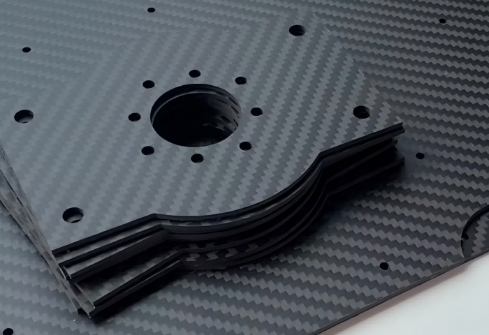
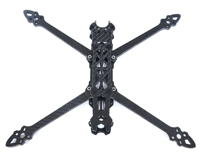
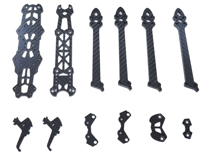
Mark4 V2 Mark4 7inch 295mm / 8inch 367mm / 9inch 387mm / 10inch 427mm 3K Full Carbon Fiber TrueX Frame for FPV Camera Kit Done:


Carbon Fiber FPV Drone Frame,FPV Drone TrueX Frame,Carbon Fiber FPV Frame
Jiangsu Yunbo Intelligent Technology Co., Ltd , https://www.fmodel-ai.com