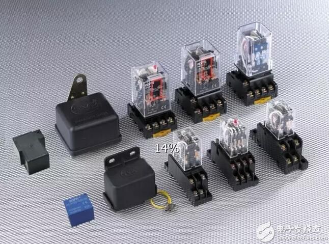
The relay is an automatic switching element with isolation function. It is widely used in remote control, telemetry, communication, automatic control, mechatronics and power equipment. It is one of the most important control components. A relay is actually an "automatic switch" that uses a small current to control a large current. Therefore, it plays the role of automatic adjustment, safety protection and conversion circuit in the circuit.
Relay characteristics of the relay:
The input signal x of the relay is continuously increased from zero to the action value xx when the armature starts to pick up. The output signal of the relay immediately jumps from y=0 to y=ym, that is, the normally open contact is disconnected to open. Once the contact is closed, the input x continues to increase and the output signal y will no longer change. When the input quantity x drops from a value greater than xx to xf, the relay begins to release and the normally open contact opens. We call this characteristic of the relay a relay characteristic, also called the input-output characteristic of the relay.
First, the working principle and characteristics of the relay (relay) 1, the working principle and characteristics of the electromagnetic relay
Electromagnetic relays are generally composed of a core, a coil, an armature, a contact spring, and the like.
As long as a certain voltage is applied to both ends of the coil, a certain current flows in the coil, thereby generating an electromagnetic effect, and the armature will absorb the pulling force of the return spring against the iron core under the action of the electromagnetic force attraction, thereby driving the armature. The moving contact is in contact with the stationary contact (normally open contact).
When the coil is de-energized, the electromagnetic suction force also disappears, and the armature returns to the original position in the reaction force of the spring, so that the movable contact and the original static contact (normally closed contact) are released. In this way, the suction and release are achieved, thereby achieving the purpose of turning on and off in the circuit.
For the "normally open, normally closed" contacts of the relay, it can be distinguished as follows: a static contact that is in an open state when the relay coil is not energized, called a "normally open contact"; a static contact that is in an on state It is a "normally closed contact".
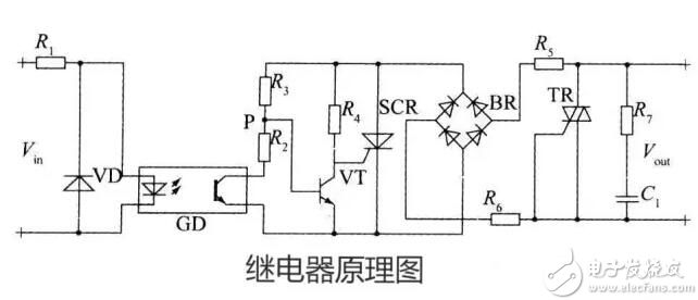
2, the circuit principle 2.1 Brief introduction of the relay Relay is a kind of when the input quantity changes to a certain value, its contact (or circuit) is connected or disconnected AC and DC small capacity control loop.
2.2 Working principle
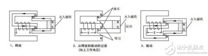
The permanent magnet keeps the release state, and after the working voltage is applied, the electromagnetic induction causes the armature and the permanent magnet to generate suction and repulsive moments, generates downward movement, and finally reaches the suction state.
3. Transistor Drive Circuit 3.1 Circuit Schematic When a transistor is used to drive a relay, an NPN transistor is recommended.
The specific circuit is as follows:
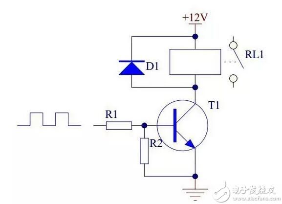
When the input level is high, the transistor T1 is saturated and the relay coil is energized, and the contacts are attracted. When the input is low, the transistor T1 is turned off, the relay coil is turned off, and the contact is turned off.
3.2 The role of each component in the circuit (1) Transistor T1 is the control switch.
(2) The resistor R1 mainly acts as a current limiting device to reduce the power consumption of the transistor T1.
(3) The resistor R2 reliably turns off the transistor T1.
(4) Diode D1 reverses the freewheeling flow, providing a bleed path for the triode to turn off from the turn-on and turn the voltage on the +12V.
4, integrated circuit drive circuit
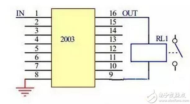
Integrated circuits integrated with multiple drive transistors have been used, and the use of such integrated circuits simplifies the design process of printed boards that drive multiple relays. The integrated circuits for driving relays nowadays mainly include TD62003AP.
When the input terminal of the 2003 is high level, the corresponding output port outputs a low level, the relay coil is energized at both ends, and the relay contacts are attracted; when the 2003 input terminal is at a low level, the corresponding output port is in a high impedance state, the relay coil The two ends are powered off and the relay contacts are disconnected.
24V relay drive circuit:
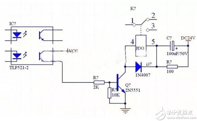
Relay series RC circuit:
This form is mainly used in circuits where the rated operating voltage of the relay is lower than the supply voltage. When the circuit is closed, the self-inductance of the relay coil will cause the electromotive force to hinder the increase of the current in the coil, thereby prolonging the pull-in time. After the RC circuit is connected in series, the pull-in time can be shortened.
The principle is that at the moment when the circuit is closed, the voltage at the voltage across the capacitor C cannot be abruptly changed as a short circuit, so that a power supply voltage higher than the rated working voltage of the relay coil is applied to the coil, thereby accelerating the speed of the current increase in the coil, so that the relay Quickly pull in. Capacitor C does not work after the power supply is stable, and resistor R acts as a current limiter.
Second, the selection of the rated working voltage of the relay The rated working voltage of the relay is the most important technical parameter of the relay.
When using a relay, you should first consider the operating voltage of the circuit in which it is located (ie, the circuit in which the relay coil is located). The rated operating voltage of the relay should be equal to the operating voltage of the circuit in which it is located.
The operating voltage of the circuit is generally 0.86 of the rated operating voltage of the relay. Note that the workpiece voltage of the circuit should not exceed the rated working voltage of the relay, otherwise the relay coil is easy to burn.
In addition, some integrated circuits, such as the NE555 circuit, can directly drive the relays. Some integrated circuits, such as COMS circuits, have a small output current. A transistor amplifier circuit is required to drive the relay. This should consider that the transistor output current should be greater than The rated operating current of the relay.
When a transistor is used to drive a relay, the emitter of the transistor must be grounded. The specific circuit is as follows:
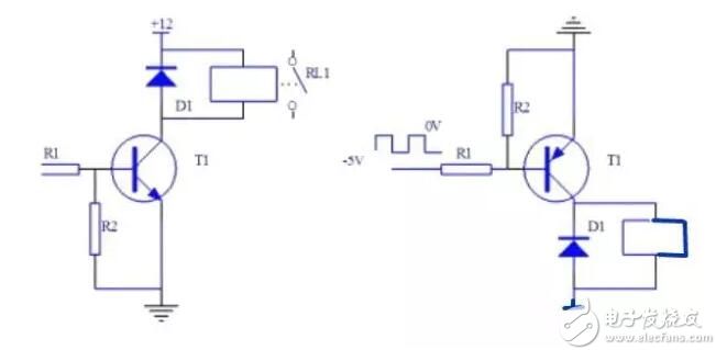
When the NPN transistor is driven:
When the base of the transistor T1 is input to a high level, the transistor is saturated and the collector is turned to a low level, so that the relay coil is energized and the contact RL1 is attracted.
When the base of transistor T1 is input low, the transistor is turned off, the relay coil is de-energized, and contact RL1 is turned off.
R&M Vape is so convenient, portable, and small volume, you just need to take them out of your pocket and take a puff,
feel the cloud of smoke, and the fragrance of fruit surrounding you. It's so great.
We are China leading manufacturer and supplier of Disposable Vapes puff bars, lana bar vape, LANA Vape pod, lana vape pen,
lana disposable vape pen, and e-cigarette kit, and we specialize in disposable vapes, e-cigarette vape pens, e-cigarette kits, etc.
r&m vape, r and m vape, r&m legend vape, r and m vapes for smoking
Ningbo Autrends International Trade Co.,Ltd. , https://www.vapee-cigarettes.com