Have you ever encountered occasional communication errors when debugging with CAN or rs-485/' target='_blank'>RS-485 bus? Or can't receive data? A bus that has been in normal use, suddenly has a wide range of errors, or node damage? Are you still overwhelmed by these problems and can't figure it out? Using bus isolation may be able to solve the problem easily.
In the actual bus application, have you encountered the following problems:
The use environment of CAN and RS-485 bus is very complicated, and there are high voltages in some bad use cases. It is extremely prone to electric shock and endangers the safety of people or equipment.
2, the remote end can not receive the data - the ground potential difference existsIn many practical applications, the communication distance can reach several kilometers, and the distance between nodes is very far. Designers often connect the reference ground of each node directly to the local land, as the return of the signal, it seems normal and reliable, but there are great hidden dangers! Even if you debug a normal system, you may have various problems after using it for a while.
A problem that is often overlooked is that there may be a large potential difference between the two nodes! ! ! The actual earth is not an ideal "0" potential, the earth is also a conductor, and there is also impedance. When a large current flows through the earth, there is also a potential difference across the ground where the current flows. As shown in Figure 1.
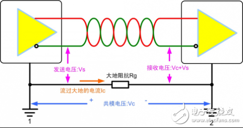
figure 1
If the communication nodes that are far apart are directly connected to their respective local earths, the ground potential difference will be superimposed on the output of the bus transmitter in the form of common mode voltage. The signal after superposition may far exceed the total of the receiver. The modulo input voltage range prevents the signal from being received properly and can seriously damage the transceiver. The common CAN and RS-485 transceivers have a small common-mode input range. For example, the SN65HVD251 and SP3085 transceivers only support the -7~+12V common-mode input range, and the ground flows through the large currents injected by various large devices. The resulting ground potential difference can be as high as a few volts, tens of volts, or even hundreds of volts, well beyond the range of voltages that the transceiver can withstand.
3. Data errors without warning, or device damage - ground loop effectsSince there is a potential difference between the nodes, it is not enough to connect the two nodes directly with one line. Big mistake! This can only make the situation worse. This long wire will form a great loop with the earth!
I believe that everyone knows in the student days that a closed coil will generate current in a changing magnetic field. 50Hz AC power lines, large motors, etc., are all sources of AC magnetic fields. If the bus approaches or passes through these places, the ground loop will generate currents up to several amps or even hundreds of amps. The common mode voltage generated by current flowing through the ground loop affects the normal communication of the bus.
In addition to a stable source of magnetic fields, transients such as surges, lightning strikes, and high-frequency noise on some power lines are likely to be picked up by this giant "loop antenna" and cause communication anomalies.
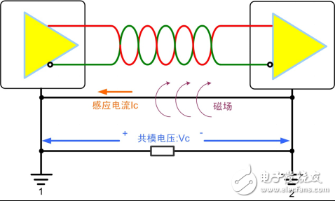
figure 2
What should I do if I encounter these problems?Replace the CAN and RS-485 transceivers you are using with isolated CAN and RS-485 transceivers!
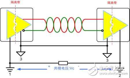
The isolated transceiver electrically isolates the bus from the control circuitry, blocking high voltages out of the control system, and effectively protecting the operator's personal and system safety. Not only that, isolation can suppress various common mode interference caused by ground potential difference and ground loop, ensuring uninterrupted and error-free operation of the bus in the presence of severe interference and other system-level noise. As shown in Figure 3, after using the isolated transceiver, the ground loop can be effectively prevented. The bus reference ground can fluctuate following the fluctuation of the common mode voltage. The common mode voltage is fully absorbed by the isolation band, and the common mode voltage becomes the bus signal. It is no longer visible, ensuring that the bus communicates reliably and reliably.
Power analyzer power calculation method already exists
Why are OEMs paying more and more attention to CAN conformance testing? existed
5. How to achieve isolation?There are two main methods for implementing bus isolation. One is to isolate the node from the transceiver by using discrete DC-DC, optocoupler and other discrete devices. Using this method, the circuit is more complicated and larger, and it is difficult to meet the high integration requirements of current electronic products. The other is to use the isolated transceiver directly, a single product, simple design and high integration.
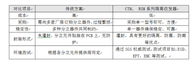
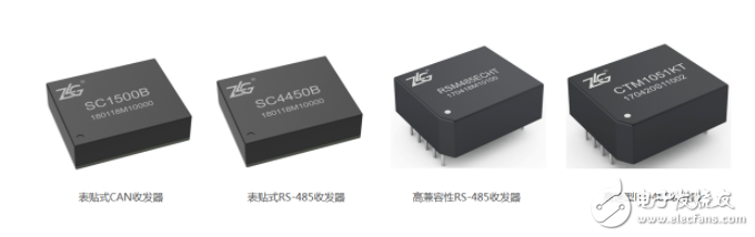
ZLG Zhiyuan Electronics specializes in the research and development of isolated power and isolated communication products. Its CTM and RSM series isolated transceivers have been widely recognized in the market. These products retain the design philosophy of traditional isolation circuits, including power isolation and electrical isolation. More importantly, the perfect test system and advanced technology ensure product consistency, with many advantages such as waterproof, shockproof and extended service life. The product uses a potting process to continuously protect the board and electronic components from moisture, vibration, overheating, corrosion and radiation, extending the life of the product. The use of integrated communication isolation modules gives customers a higher value than discrete component designs, as shown in Table 1.
Table 1 Comparison of schemes
ZLG Zhiyuan Electronics provides you with high quality and reliable isolated CAN transceiver, isolated RS-485 transceiver, power and signal isolation, isolation withstand voltage up to 2500VDC and above, can protect your CAN, RS-485 bus!
GPS Tracker, Locator for Precious Assets.
Features that already exist
âš« Tracking: It sends GPS (Location, speed) and sensors (if any) information to your application server with configurable report interval (moving or stationary).
âš« Geofence: It supports circle and polygon setting.
âš« Backup Battery (optional): With a backup battery (300mAh), the device sends a tamper message if the main power supply harness is disconnected.
âš« 3-Axis Accelerometer: With a built-in 3-axis accelerometer, the device can detect trip start/trip end, and to report harsh braking, harsh acceleration, and impact.
âš« Storing Message: The device stores up to hundreds of messages while there is no GSM signal.
âš« Low Voltage Detection (optional): Device switches to deep sleep mode if supply voltage drops below a threshold.
âš« Power Saving Mode: Device periodically wakes up and sleeps when vehicle engine is OFF.
âš« OTA (Over the Air): The device`s firmware can be upgraded via TCP.
âš« Waterproof Case: IPX65 waterproof
âš« Bluetooth-positioning: It will support bluetooth feature for positioning.
âš« Mileage: Reports trip start, trip end and the mileage.
âš« Moving Wakeup: Device will automatically wakeup when it senses moving of the asset and power down itself when it is stationâš« Drop Alarm: Using embedded light sensor to detect the drop/detach from the tracking object.
âš« Cell-ID Based Location: Device reports cell-ID based location information where
âš« Flexible battery selection
Other functions can be customized.
Asset GPS Trackers,Wireless GPS Trackers,4G asset GPS trackers,LTE asset GPS Trackers,Waterproof GPS Trackers
eSky wireless Inc , https://www.eskygpsiot.com