Figure (1) is the simplest rectifier circuit. It consists of a power transformer B, a rectifier diode D and a load resistor Rfz. The transformer converts the mains voltage (mostly 220 volts) into the required alternating voltage E2, which in turn converts the alternating current into pulsating direct current.
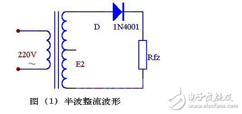
From the waveform of Figure (2) we can see how the diode is rectified:
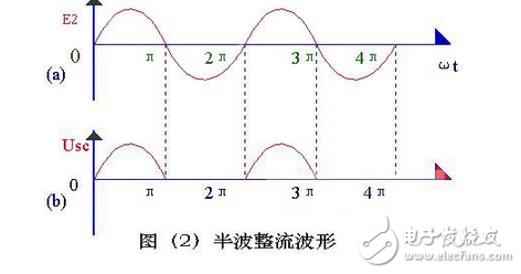
The transformer cut-off voltage E2 is a sine wave voltage whose direction and magnitude change with time, and its waveform is shown in (2) (a). During the period from 0 to π, E2 is a positive half cycle, that is, the upper end of the transformer is negative at the lower end. At this time, the diode is subjected to the forward voltage surface conduction, and E2 is applied to the load resistor Rfz through it. In the period of π~2π, E2 is a negative half cycle, and the lower end of the transformer is positive and the upper end is negative. At this time, D is subjected to reverse voltage, no conduction, and no voltage on Rfz. In the period of 2π to 3π, the process of 0 to π time is repeated, and in the period of 3π to 4π, the process of π to 2π time is repeated... This is repeated, and the negative half cycle of the alternating current is "cut", only positive Half-cycle through Rfz, a single right-direction (upper-down-down) voltage is obtained on Rfz, as shown in Figure 5-2(b), for rectification purposes, however, the load voltage Usc. And the magnitude of the load current also varies with time, so it is often referred to as pulsating DC.
(2) full wave rectificationIf the structure of the rectifier circuit is adjusted, a full-wave rectifier circuit that can fully utilize the power can be obtained. Figure (3) is an electrical schematic of the full-wave rectification circuit.
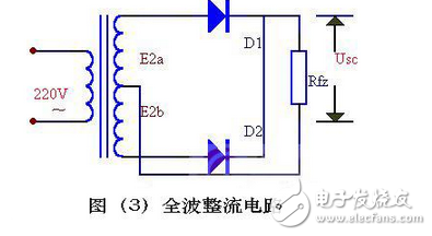
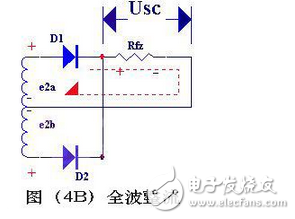
The full-wave rectification circuit can be considered as a combination of two half-wave rectification circuits. In the middle of the secondary winding of the transformer, a tap is drawn to divide the secondary coil into two symmetrical windings, thereby extracting two equal-sized but opposite-polarized voltages E2a and E2b, which constitute E2a, D1, Rfz and E2b, D2, Rfz, Two energized circuits.
The working principle of the full-wave rectification circuit can be illustrated by the waveform diagram shown in Figure (4). In the range of 0 to π, E2a is a forward voltage to D1, D1 is turned on, and a positive and negative voltage is obtained on Rfz; E2b is a reverse voltage for D2, and D2 is not conducting, see (4b). In π-2π time, E2b is forward voltage for D2, D2 is turned on, and the voltage obtained on Rfz is still positive and negative; E2a is reverse voltage for D1, D1 is not conducting, see figure (4C) ).
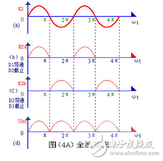
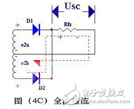
In this way, since the two rectifying elements D1 and D2 are alternately conducting, the load resistance Rfz has a current in the same direction during the positive and negative two half cycles, as shown in (4), hence the name Full-wave rectification, full-wave rectification not only utilizes the positive half cycle, but also subtly utilizes the negative half cycle, which greatly improves the rectification efficiency (Usc = 0.9e2, which is twice as large as that of the half-wave rectification).
The full-wave splicing circuit shown in Fig. (3) requires the transformer to have a secondary center tap that makes the ends symmetrical, which causes a lot of trouble in production. In addition, in this circuit, the maximum reverse voltage that each rectifier diode is subjected to is twice the maximum value of the secondary voltage of the transformer, so a diode capable of withstanding higher voltages is required.
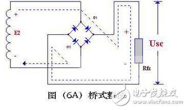
(3) Bridge rectifierThe bridge rectifier circuit is the most used rectifier circuit. Such a circuit, as long as two diode ports are connected to form a "bridge" structure, has the advantages of a full-wave rectification circuit, while at the same time overcoming its disadvantages to some extent.
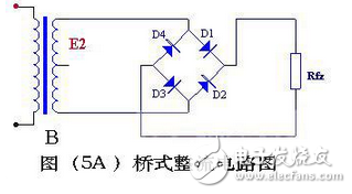
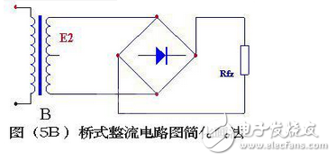
The working principle of the bridge rectifier circuit is as follows: when E2 is positive half cycle, D1, D3 and directional voltage, Dl, D3 are turned on; reverse voltage is applied to D2 and D4, D2 and D4 are cut off, and E2 and D1 are formed in the circuit. Rfz, D3 energized loop, on the Rfz, form a half-wave flushing voltage that is positive and negative, as shown in Figure (6A); when E2 is negative half-cycle, add forward voltage to D2 and D4, and D2 and D4 turn on; D1 and D3 are added with reverse voltage, and D1 and D3 are cut off. In the circuit, E2, D2, Rfz, and D4 are energized, and the rectified voltage of the other half of the upper and lower negative is also formed on Rfz, as shown in Fig. 6B.
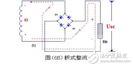
Repeating this way, the result is a full-wave rectified voltage at Rfz. The waveform is the same as the full-wave rectified waveform. It is not difficult to see from figures (6A) and (6B) that the reverse voltage of each diode in the bridge circuit is equal to the maximum value of the secondary voltage of the transformer, which is half the size of the full-wave rinsing circuit!
In addition, it should be specially pointed out that the diode as a rectifying component should be selected according to different rectification methods and load sizes. If improperly selected, it may not work safely, or even burn the pipe, or use it in a small amount, resulting in waste.
The above is the principle and characteristics of three different rectification methods.
Twinkle System Technology Co Ltd , https://www.pickingbylight.com