Almost all measuring instruments that require waveform display face a problem: the number of sampling points in the waveform segment to be displayed is not equal to the number of pixels in the screen display area. In this case, how to draw the waveform into the display area? This article will introduce you to several solutions to this problem.
In the first case, the number of sampling points in the waveform segment is larger than the number of pixels in the screen display area. In different cases, the extraction scheme used is different.
Equal interval extraction
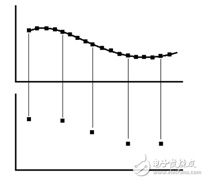
Figure 1 isometric extraction
This is actually a question of how to compress a large number of waveforms to a specific number of points. For this problem, we can naturally think of using equal-space waveform extraction. The sampling points are extracted at equal intervals with a fixed ratio of the number of sampling points of the waveform segment to the number of screen points, and the extracted sampling points are displayed on the screen. The advantage of this scheme is that it achieves a simple and responsive outline of the waveform, which is suitable for signals with lower frequencies. The disadvantage is that for signals with too high frequency, the peaks are filtered out and cannot reflect the peak value of the signal.
2. Peak extraction
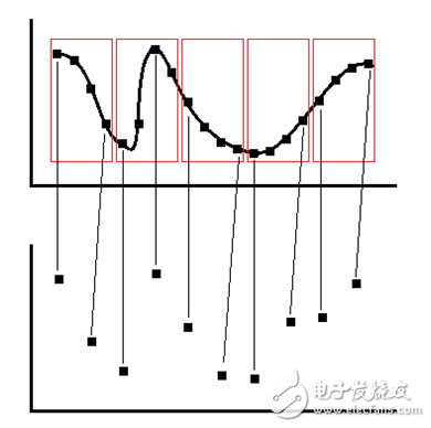
Figure 2 Peak extraction
The peak extraction is to divide the original sampling segments of the waveform into several groups, which are divided into five groups as shown in the figure. Each group compares the maximum value and the minimum value as extraction points, and maintains the order relationship of the two points. This extraction method is directed to high frequency signals, and has the advantage of finding peaks, but does not guarantee equal time intervals between adjacent points.
3. Mean extraction
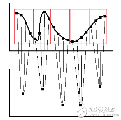
Figure 3 Mean extraction
The mean extraction also divides the original sampled waveform into segments, each of which calculates an average value as the extraction point for the segment. This scheme can be considered as a compromise between the first two schemes. By averaging, the time interval between adjacent points is ensured to be equal, and the extracted waveform is kept as consistent as possible with the original waveform; however, there are also Signals, peaks are filtered out and do not reflect the peak value of the signal.
Let us look at the second case: the number of samples in the waveform segment is less than the number of pixels in the display area of ​​the screen.
This situation needs to be solved by filling the fictitious sampling points between the sampling points.
Direct fill
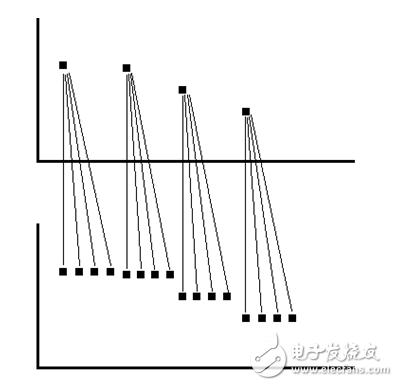
Figure 4 direct fill
Copy the previous real sample point directly at the location where you need to fill the fictitious sample point. This solution is simple to implement, and the disadvantage is that the waveform is stepped and unreal.
2. Linear padding
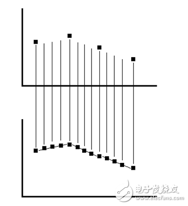
Figure 5 linear fill
The linear fill first connects adjacent sample points and then finds the filled points from the corresponding positions of the adjacent connected lines. This kind of scheme does not produce the ladder in the first scheme, but it still artificially produces nonlinear phenomena.
Sinusoidal filling
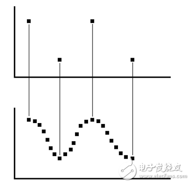
Figure 6 sinusoidal filling
Sinusoidal filling is also called sinusoidal interpolation, which is used for the restoration of signals during high-speed sampling. The specific implementation requires filtering. This kind of scheme implementation method is more complicated than the first two, but it avoids the nonlinear phenomenon better.
For diifferent USB types, micro USB, mini USB, etc. The logo, color or shape can all made as customers' requirement. With more than ten years of experience and capabilities assisting our customers in various industry, ETOP would be confident to be your qualified AVL and reliable manufacturing partner.
Related Products:usb cable,micro usb cable,usb Data Cable.
Data Cable
Data Cable,Data Flexible Electrical Magnetic Cable,Usb Data Cable,Micro Usb Cable,USB Connector
ETOP WIREHARNESS LIMITED , http://www.oemwireharness.com