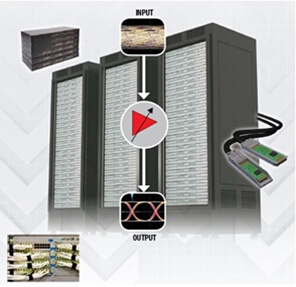
This article describes how to extend the Serial Peripheral Interface (SPI) bus through a differential interface, which can be applied to systems that support remote temperature or pressure sensors.
In SPI applications, the distance between the master and the controlled device is relatively close, and the signal is usually not passed outside the printed circuit board (PCB). The SPI signal is similar to a single-ended, Transistor-Transistor Logic (TTL) signal that can operate at speeds up to 100Mbps, depending on the application. An SPI bus consists of four signals: the system clock (SCLK), the master output slave input (MOSI), the master input slave output (MISO), and the chip select (CS). The master device provides the SCLK, MOSI and CS signals, while the controlled device provides the MISO signal. Figure 1 shows the bus architecture of a standard SPI bus.

Figure 1: SPI bus
If the user needs to send an SPI signal from your microcontroller or digital signal processor (DSP) to a remote board outside the board (including an analog-to-digital converter (ADC), a digital-to-analog converter (DAC) or What about other devices?) What should I do?
This type of operation is challenging for several reasons.
The first reflection caused by unterminated signal lines can seriously affect signal integrity. The characteristic impedance and termination impedance of the transmission medium vary widely, causing impedance mismatch on the bus. The result will be a standing wave of energy radiating from one end of the bus to the other, resulting in communication errors. Electromagnetic interference (EMI) is also a problem because the high-frequency portion of the SPI signal radiates outward, causing this signal to confuse with adjacent signals.
But here's a simple solution: use a differential signal. Differential transceivers such as the SN65LVDT41 and SN65LVDT14 receive SPI signals and convert them to low voltage differential signaling (LVDS). Due to its noise immunity and bandwidth, LVDS works well in SPI applications. An article in the previous "Get Connected" blog discussed the basic principles and advantages of LVDS; click here to view this article.
The architecture of the SN65LVDT41 and SN65LVDT14 allows the entire SPI bus to be converted to support LVDS: 4 transceivers for MOSI, SCLK and CS signals in the same direction, and 1 transceiver for MISO signals in the opposite direction. The LVDS chipset also has the added advantage of a built-in termination, which is simple to use and reduces the number of components in an application that is inherently valuable in board space. Figure 2 shows the structure of an extended SPI bus architecture using the chipset described above. This implementation does not require the use of Category 5 Shielded Twisted Pair (STP), but the use of such a cable will make this architecture easier to implement.
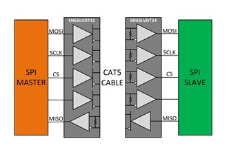
Figure 2: Extended SPI bus
Figures 3, 4 and 5 show the performance of the SN65LVDT41 and SN65LVDT14 transmitters at a transmission speed of 100 Mbps over several times the length of the Category 5 line. The receivers in the SN65LVDT41 and SN65LVDT14 support a 200mV input withstand threshold, and transmitters at these distances and speeds can easily meet this tolerance threshold.
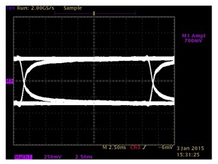
Figure 3: 8 Mbps Category 5 Line 100 Mbps TX Waveform 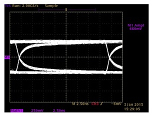
Figure 4: 100Mbps TX waveform of 15m Category 5 line 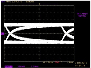
Figure 5: 100Mbps TX waveform of 25m Category 5 line
You can find common interface design questions in the Interface/Clock section of the Texas Instruments Online Support community; read posts written by engineers who have used TI interface products, or create solutions or ideas that will meet your specific application needs; With no connectivity yet, you can connect using TI's extensive portfolio of interfaces, which includes a wide range of interface standards and applications and connects them together.
The FirstPower Long Life Battery is desgined for apllcation as General Purpose and long life. The series focus on improving trickle life that base on Standard series.
We welcome orders with "FirstPower" brand; We are also flexible to accept orders on OEM basis. Contact us now! Your partnership with FirstPower will prove worthy of it.
Long Life Battery
Long Life Battery,Gps Tracker Long Life Battery,Long Life Electric Scooter Battery
Firstpower Tech. Co., Ltd. , https://www.firstpowersales.com