To do power supply design, or to do the drive circuit, it is inevitable to use FET, which is often referred to as MOS tube. There are many types of MOS tubes, and there are many functions. To use the power supply or the driver, of course, is to use its switching function.
Regardless of the N-type or P-type MOS tube, the working principle is essentially the same. The MOS transistor controls the current at the output drain by the voltage applied to the input gate. The MOS transistor is a voltage-controlled device that controls the characteristics of the device by the voltage applied to the gate, and does not cause a charge storage effect due to the base current when the transistor is switched. Therefore, in the switching application, the switching speed of the MOS transistor It should be faster than a triode. The main principle is shown in Figure 1.
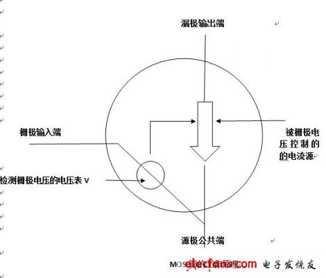
Figure 1 MOS tube works
We use the open-drain circuit of the MOS transistor in the switching power supply. As shown in Figure 2, the drain is connected to the load as it is, called the open-drain, and the open-drain circuit can be turned on and off regardless of the voltage of the load. Break load current. It is an ideal analog switching device. This is the principle that MOS tubes are used as switching devices. Of course, the circuit form used by the MOS tube as a switch is much more.
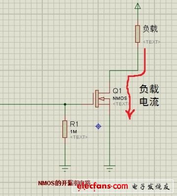
Figure 2 Open drain circuit of NMOS transistor
In switching power supply applications, this application requires the MOSFET to be turned on and off periodically. For example, the basic buck converter commonly used in DC-DC power supplies relies on two MOS transistors to perform switching functions that alternately store energy in the inductor and then release the energy to the load. We often choose frequencies from hundreds of kHz to more than 1 MHz, because the higher the frequency, the smaller and lighter the magnetic components. During normal operation, the MOS tube is only equivalent to one conductor. Therefore, our circuit or power supply designers are most concerned about the minimum conduction loss of MOS.
We often look at the PDF parameters of MOS tubes. MOS tube manufacturers use RDS(ON) parameters to define the on-resistance. For switching applications, RDS(ON) is also the most important device characteristic. The data sheet defines RDS(ON) as a function of the gate (or drive) voltage VGS and the current flowing through the switch, but for adequate gate drive, RDS(ON) is a relatively static parameter. The MOS tube that has been turned on is prone to heat. In addition, a slowly rising junction temperature will also result in an increase in RDS(ON). The MOS tube data sheet specifies the thermal impedance parameter, which is defined as the heat dissipation capability of the semiconductor junction of the MOS tube package. The simplest definition of RθJC is the thermal impedance of the junction to the envelope.
1. The heating situation is, the problem of circuit design is to let the MOS tube work in a linear working state, not in the switching state. This is also a cause of heat in the MOS tube. If the N-MOS is switched, the G-level voltage is a few V higher than the power supply to be fully turned on, and the P-MOS is the opposite. The power consumption is not fully opened and the voltage drop is too large, the equivalent DC impedance is relatively large, and the voltage drop is increased, so U*I also increases, and the loss means heat. This is the most taboo error in designing circuits.
2, the frequency is too high, mainly because the volume is excessively pursued, resulting in an increase in frequency, the loss on the MOS tube is increased, so the heat is also increased.
3, did not do enough heat dissipation design, the current is too high, the nominal current value of the MOS tube, generally requires good heat dissipation to achieve. Therefore, the ID is less than the maximum current, and it may cause severe heat generation, and sufficient auxiliary heat sink is required.
4, MOS tube selection is wrong, the power is judged incorrectly, the MOS tube internal resistance is not fully considered, resulting in increased switch impedance
This is a simple summary of my recent dealing with MOS tube heating problems. In fact, these problems are also common problems. Switching power supply or MOS tube switch driving should be familiar with the knowledge. Of course, there are other factors, mainly for the above reasons.
Indoor air in a healthcare environment is a veritable invisible cloud of particulate matter, microorganisms (including spores, viruses and bacteria) and volatile organic compounds (emitted by cleaning products and furniture) dust, lint from hospital linens and fabrics, surgical smoke, and even pollen and animal dander brought in on the clothes of staff, patients and visitors. Traces of chemicals, gases and fumes can also be present.
Our Advanced product is specially designed for Air Sterilization for Hospitals.
We used the 3-in-1 technique (Semiconductor, UV and HEPA Filter) in the Air Sterilizer to eliminate bacteria, dust, odour or micro organisms.
Air Sterilizer
Air Sterilizer,Ozone Air Sterilizer,Air Purifier Sterilizer,Ultraviolet Air Sterilizer
Dongguan V1 Environmental Technology Co., Ltd. , https://www.v1airpurifier.com