0 Introduction In recent years, the rapid development of electronic technology has made embedded systems more and more widely used. The functions of the embedded system platform are also becoming more and more powerful, and the complexity is getting higher and higher, and the difficulty and requirements for its development are getting higher and higher. In the development process, application software and system software need to be considered as a whole, and the connection between software and hardware is closer. Therefore, the development of embedded systems is a complex process. With the dramatic improvement in the performance of embedded systems, the old-fashioned GPS navigator has begun to develop in the embedded direction. Embedded GPs navigators have become more and more portable, and their functions are becoming more and more powerful. Voice navigation and media functions have become a prominent highlight of embedded GPS navigators. Therefore, MP3 audio decoding and playback technology has become a basic technology in embedded GPS navigation systems. The full name of MP3 is MPEG Audio Layer 3, which is a popular audio coding scheme. It is part of the MPEG-1 standard, which was developed in 1992. The MPEG standard consists of three parts: system, video and sound. The sound standard is divided into three layers, and MP3 is the third layer. It is the layer with the highest computational complexity and the best compression effect. Compared to the traditional CD format, the sound effect is almost the same, but the amount of data is less than one tenth of the CD. At the same time, the portability and endurance of the MP3 player are greatly improved compared to the CD. MP3 was originally used in digital audio broadcasting and digital TV audio; later, with its popularity, MP3 formats have been used in other places, especially Internet music and portable entertainment devices; now, almost all portable voice navigation Devices use MP3 as their audio media format. This paper mainly introduces the decoding technology of MP3 audio files under the embedded GPS navigation system platform based on ARM core. In order to take advantage of the self-designed solution in Windows CE. Under the NET system, Samsung's S3C2410 platform is used to realize the decoding and playback function of MP3.
This article refers to the address: http://
1 MP3 decoding principle
1.1 MP3 file format MP3 files consist of a number of mutually independent frames, each frame contains 1152 sample information, one MP3 frame contains frame header, error check, audio data and auxiliary data. section. FIG. 1 is a schematic diagram of a frame structure of an MP3. The last 128 bytes of an MP3 file usually contain an ID3v1 tag with additional user-customized file extensions such as song title, artist, style description, and so on.

1.2 MP3 decoding process The original PCM (Pulse Code Modulation) audio data will be MP3 code stream after compression encoding. MP3 decoding is to restore the MP3 code stream to the original PCM data. The MP3 data is in units of frames. The decoding should first find the position of the MP3 frame in the code stream according to the synchronization information and the error check CRC module, and thereby determine the position of the frame header, the CRC check, the audio data and the auxiliary data.
Figure 2 shows the decoding process of MP3, which mainly includes Huffman decoding, inverse quantization, de-reordering, stereo decoding, aliasing cancellation, IMDCT, frequency inversion compensation, sub-band synthesis filtering, and the like. The role of the pre-processing in Figure 2 is to read the header data and store the required information in a structure for subsequent decoding.
When Huffman decodes, MP3's audio data will be divided into two sections (gxanule). These two sections are relatively independent in process encoding and decoding. Each section can decode 576 PCM sampling data, and two sections can solve 1152. Sample data. The first step in getting the information we need from the binary 101...code stream is to solve the Huffman code. The Huffman code is a table lookup process. These 576 values ​​represent values ​​on 576 frequency lines. They have different meanings in different blocks (for example). The corresponding codes can be found according to different scale factors and frequency bands. The table solves 576 values.
The inverse quantization process uses different inverse quantization formulas for long blocks, short blocks, and mixed blocks based on the inverse quantization formula and frame side information to recover the true value of 576 frequency lines. The purpose of anti-reordering is to make the MP3 encoder make Huffman coding more efficient and reorder some blocks. The function of the stereo decoding section is to perform stereo decoding when the two audio channels are not independently encoded.
Aliasing cancellation is to avoid aliasing between two adjacent sub-bands and aliasing cancellation during decoding. The role of IMDCT is firstly to perform IMDCT transformation from 18 to 36 points for long blocks and 3 G to 12 points for IMDCT transformation of short blocks. Secondly, different window types are used to add according to different block types. window. At the same time, the first half of the 36 values ​​are superimposed with the second half of the previous frame. The second half of the current block is stored for superposition with the next block. The frequency inversion compensation is the frequency inversion compensation for the multiple filter banks before going to the next step, that is, the inverse of the odd time samples of the odd subbands.
Subband synthesis filtering is to inversely transform the frequency domain signals in 32 equal frequency bandwidths into time domain signals, and then perform windowing operation to obtain 32 PCM values.
2 hardware design
2.1 System hardware design In the choice of processor, this system uses SAMSUNG company's S3C2410. It is a 16/32-bit reduced instruction set microcontroller based on the ARM920T core, a low-cost, high-efficiency microcontroller for handheld and general purpose devices. The S3C2410 ARM chip is mainly used in the design process of the whole system hardware. The SD or MMC memory card module is expanded by the storage device, and the 320x240 pixel true color TFT LCD screen is externally displayed. The control adopts a four-wire resistive touch screen and is supplemented by GPIO expansion. Keyboard.
2.2 Audio hardware design IIS (Inter-IC Sound) bus is a serial digital audio bus protocol proposed by Philips. It is an audio bus for multimedia applications dedicated to data transfer between audio devices, ie transferring PCM audio data to a standard codec (CODEC). The IIS bus only processes sound data, and other signals (such as control signals) must be transmitted separately. In order to minimize the number of outgoing pins of the circuit, IIS uses only three serial buses, that is, a data line that provides time division multiplexing, a left and right channel selection line, and a clock signal line.
The CODEC chip is mainly responsible for the mutual conversion of analog signals and digital signals. For this system, more concerned is to convert the digital PCM signal into an analog signal, mainly to send the audio digital signal of the file to be played to the CODEC chip through the IIS of the SC2410, and then convert it into an analog signal, and then through the speaker or Device output such as headphones.
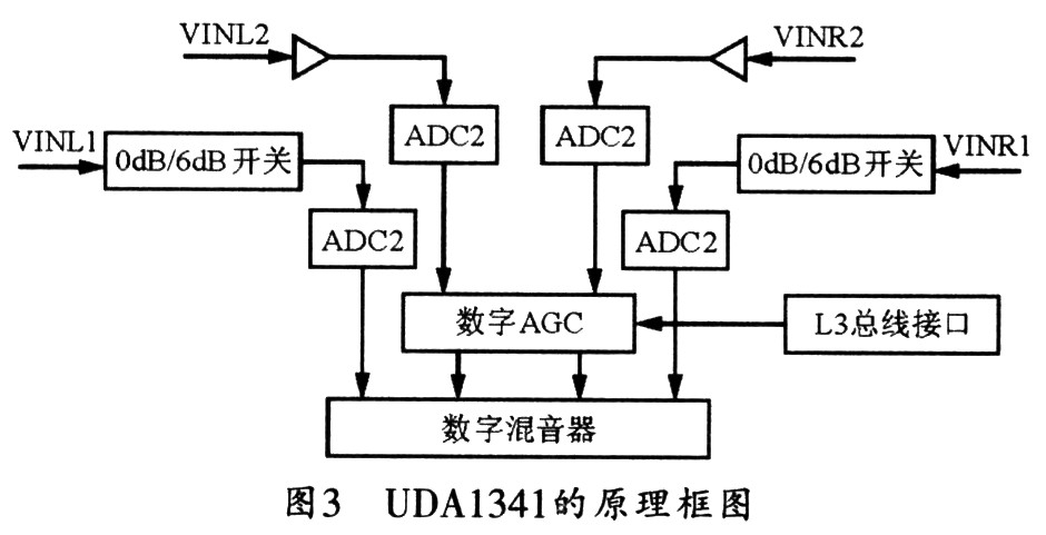
According to the sampling theorem, the sampling frequency should be at least twice the signal frequency, and then the IIS interface standard should be supported, because the system transmits data to the CODEC chip through the IIS bus. In the CODEC of this system, Philips U-DA1341 is selected. The chip is powered by 3.0 V and supplies power to the ADC and DAC respectively. The clock frequency of the system can be 256fs, 348fs and 512fs, and the sampling frequency is from 16 kHz to 48. kHz, due to the digital sound quality control, has a bass effect and supports the IIS bus to ensure high-fidelity stereo output. Figure 3 shows the working principle block diagram of the UDA1341.
The hardware design of the entire audio system is mainly the connection and implementation of the S3C2410 IIS bus interface and CODEC. The specific circuit is shown in Figure 4. This system uses Philips UDA1341 audio CODEC chip based on IIS audio bus. The CODEC supports the IIS bus data format and uses bitstream conversion technology for signal processing, with a programmable gain amplifier (PGA) and a digital automatic gain controller (AGC).
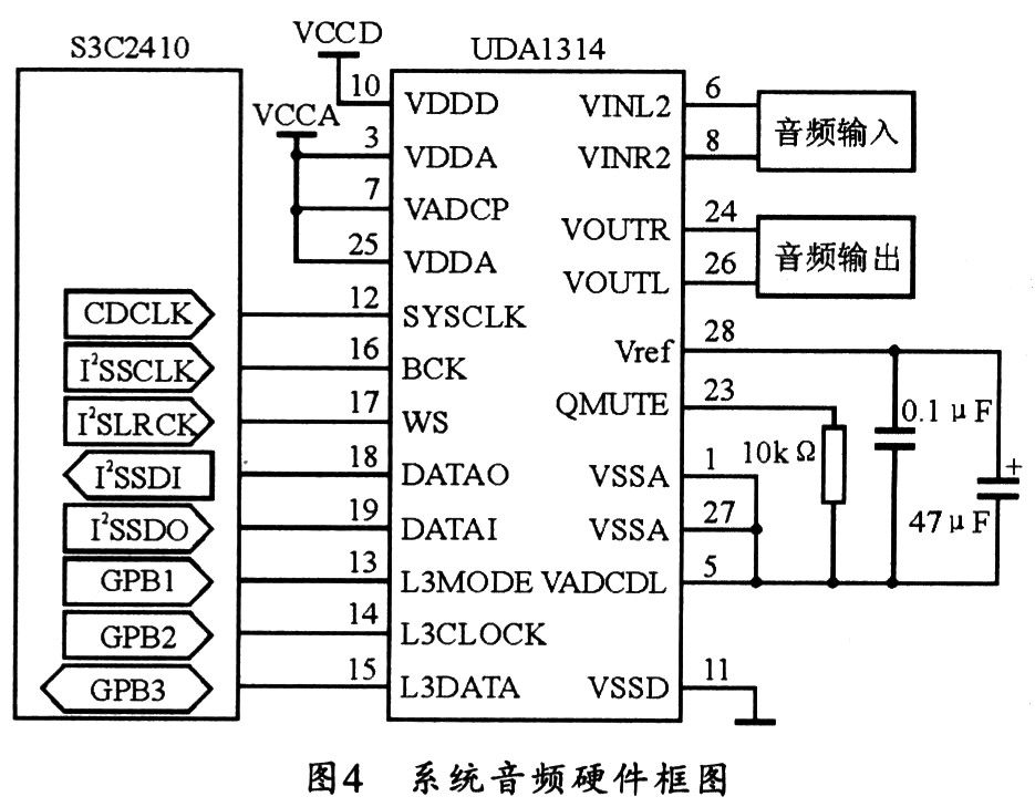
The S3C2410 has an IIS bus interface that can directly connect an 8/16-bit stereo CODEC. It can also provide a DMA transfer mode instead of an interrupt mode for the FIFO channel, allowing data transmission and reception to occur simultaneously. The IIS interface has three working modes, which can be selected by setting the CON register of IIS. The hardware framework described in this article is based primarily on the transmit and receive modes. In this mode, the IIS data line will receive and transmit audio data simultaneously through the dual channel DMA, and its DMA service request can be automatically completed by the FIFO read-only register.
In Figure 4, the IIS bus signal of the S3C2410 is directly connected to the IIS signal of the UDA1341. The L3 interface pins L3MODE, L3CLOCK and L3DATA are respectively connected to the three general data output pins of the S3-C2410 GP-B1, GPB2 and GPB3. The U-DA1341 provides two sets of audio signal input interfaces, each of which includes two left and right channels.
3 software design
3.1 Choice of system platform At present, the mainstream embedded platforms mainly include two series of embedded Linux and Windows CE.
Linux is a Unix-like operating system. It originated from a Finnish amateur named Linus Torvalds, but is now the most popular open source free operating system. Linux has been developed since 1991 and has evolved into a powerful, well-designed operating system. The Linux OS, which has evolved along with advances in network technology, has become a strong rival to Mi-crosoft's Windows system. Linux systems can not only run on PC platforms, but also shine on embedded systems. Many embedded platforms use Linux as their operating system.
Windows CE is an open, scalable 32-bit embedded real-time operating system developed by Microsoft. Among them, C in CE stands for Compact, Consumer, Connectivity and Companion; E stands for Electronics. Unlike Windows for desktops, Microsoft rewrote the Windows CE kernel, which gives WindowsCE superior real-time performance. The API in Windows CE is a reduced WIN32 API, which is a subset of the desktop Windows system. This allows many applications based on Microsoft Desktop Windows to be used in Windows CE with a few changes. At the same time, on the Windows CE system platform, you can also use the programming tool language (such as VB, VC++, etc.) on the desktop Windows, and use the same function and the same interface style. Therefore, its development work is relatively easy to use. Consider the habit of most users who have used the Windows family of operating systems for many years. The interface style of Windows CE is relatively easy for users to accept.
In summary. This article chooses Windows CE as the development platform of the system, and the development tool selects the EVC of the VS series.
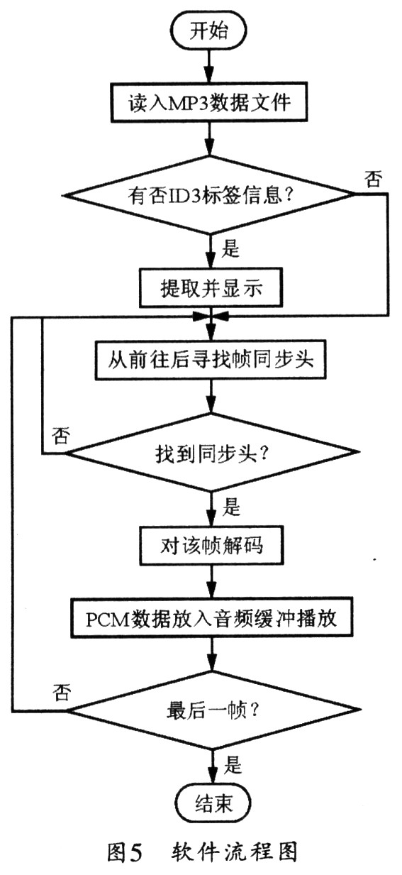
3.2 Software Flow Figure 5 shows the software flow chart for MP3 decoding. First, the MP3 file data is read by the person to look for the ID3 information in the file (ID3 information refers to an optional embedded information in the MP3 file, which is used to indicate the audio type, author, etc. of the MP3, currently divided into ID3vl and I. D3v2 The version), then look for the frame sync header in the file, and then enter the frame decoding subroutine. The specific process of frame decoding is shown in Figure 6. After the decoding is completed, the decoded PCM data is placed in the audio buffer. Play, so loop until the last frame.
The key encoding circuit uses a diode combination logic switch array to address the controlled circuit switch, wherein the instruction encoding circuit uses a compiled code chipset PT2262. The A port of the PT2262 is the address code setting port, and the D port is the data code setting end, which is respectively connected with the logic output of the diode combination logic switch array, and the data has six states from 000 to 101. The RF chip used in the transmitting module circuit is MICRF1020. When there is no signal output at the data output end of the encoding chip PT2262, the MICRF102 does not work and the emission current is zero. When the control terminal of the PT2262 is valid, the output serial pulse signal is applied to the MICRF102. Modulation emission, the modulation current R2 can adjust the emission current to adjust the emission distance, the smaller R2 value can increase the transmission distance, and the increase of the diode switch array can expand the system into a multi-channel remote control transmission module.
3.2 Receiving Control Circuit The receiving control system is mainly composed of a radio receiving circuit, a decoding circuit, a single chip circuit, and a switching circuit. The circuit schematic of the receiving control system is shown in Figure 6. The main function of the receiving control system is to demodulate and decode the incoming signal, and send the decoded data to the single-chip microcomputer, and the single-chip microcomputer controls the corresponding switch according to the data.
|

4 Conclusion This paper proposes an implementation scheme for implementing MP3 audio playback in the embedded GPS voice navigation system, gives the decoding step, and completes this scheme by using S3C2410 core and Windows CE platform. After the actual product verification, the decoder plays well. All indicators can meet the requirements.
Laptop AC adapter for common brands, such as HP, Sony, Lenovo, Dell, Asus, Toshiba, Acer, Samsung etc. Our products have high quality and reasonable price.
CE, FCC, ROHS, CCC certification are approved by our products, and it have two years warranty. Built with input/output overvoltage protection, input/output overcurrent protection, over temperature protection, over power protection and short circuit protection. We are a professional power adapter manufacturer in China. We can meet your specific requirement. We have perfect after-sale service and technical support.
Hope we can establish friendly business relationship with you in the near furture!
Laptop Adapter,Adapter For Macbook,Power Supply For Macbook, Charger For Macbook
Shenzhen Waweis Technology Co., Ltd. , http://www.waweis.com