1 Introduction
With the rapid development of microelectronics technology, embedded products have been rapidly promoted with their natural human-computer interaction interface and rich multimedia processing capabilities, and have achieved great success [1]. At present, in the field of multimedia audio, MP3 players occupy an absolute dominant position. However, the existing MP3 player has very limited driving capability and is only suitable for personal use, and cannot meet the multi-channel playback needs of playing different background music in different public places in different public places. Based on the above analysis, this paper designs a multi-channel professional MP3 player based on S3C44B0X chip in μClinux environment.
2 system function analysis and structural design
The multi-channel professional MP3 player is designed to meet the needs of the public voice broadcasting market. Its main functions include: (1) audio decoding and playback functions; and (2) data transmission via a USB interface with a large-capacity external storage device; (3) Unified management function of operation interface; (4) Multi-channel playback function.
In order to improve the system operation efficiency and realize multi-channel playback management, the system uses Samsung's S3C44B0X as the core processor, which is mainly responsible for data conversion, output channel selection, and LCD control. At the same time, ST013 of STMicroelectronics is selected as the decoding chip, and the output of analog audio signal is realized with AK4393. In addition, two main USB interfaces are provided by SL811HS and ISP1520 to realize the connection of mobile hard disk or U disk. The overall structure of the system is shown in Figure 1:
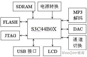
Figure 1 Overall structure of the system
3 system hardware design
As a typical embedded system, the advantage of its development lies in the tailorability of hardware and software [2]. After ensuring a stable minimum system, the peripheral devices are extended. The core chip S3C44B0X of this multi-channel professional MP3 player is a multi-function SOC (Signal Operation Control) developed based on ARM7. In addition to the bus, SDRAM controller and three serial ports of the general embedded chip, the S3C44B0X also has a TFT LCD controller, USB Slave, USB Host, I2C bus controller, SPI controller, and IIS audio interface. , SD & MMC memory card interface and other rich extension functions [3]. Since the S3C44B0X is quite mature for the main USB interface technology built by the SL811, it will not be described here. In addition, the standard interface provided by S3C44B0X can support most models of LCD display on the market, and the production is relatively simple. Therefore, this paper only explains the decoding implementation part of MP3 player and the implementation method of multi-channel.
3.1 MP3 decoding circuit design
The hardware of the decoding part of the system adopts STA013 decoding chip of ST company and AK4393 chip of AKM. STA013 is an excellent MP3 decoder chip that transmits control information over the IIC bus and voice data over a serial data line. The AK4393 is a high-quality stereo DAC chip that supports 24-bit/96KHz sampling and uses "composite bit" technology to make chip decoding faster and more accurate.
The interface part of the decoding part and S3C44B0X is shown in Figure 2. The audio data is transmitted to the STA013 through the I/O port of the S3C44B0X, and the decoding process is performed by the DSP core of the STA013. The digital audio signal decoded by STA013 is output to the D/A converter AK4393 by SDO (serial data output), SCKT (serial clock), LRCKT (left and right channel clock), and OCLK (sampling clock). The analog audio signal obtained by the AK4393 can be directly driven by the power amplifier circuit to directly drive the passive speaker.
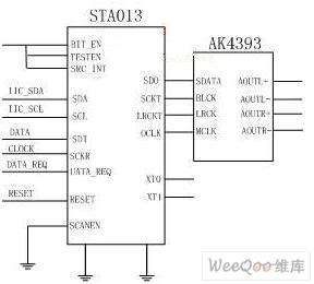
Figure 2 decoding part of the interface circuit diagram
In addition, due to the multi-channel playback format, multiple sets of identical decoder chips and DACs need to be provided during the design process.
3.2 Implementation of multi-channel functions
The basic method used for multi-channel playback of the system is (taking four channels as an example): after the system is powered on, the decoding control signal is controlled by a four-way switch (CD4066) in order to achieve specific working state control for each decoding channel. , control the working state of each channel decoding chip. The input portion of the four-way channel of the transfer switch is connected to the IICSDA of the IIC bus of the CPU, and the control data transmission direction is determined by a plurality of control pins (CTRL1, 2, 3, 4) connected to the CPU. The clock signal of the four channels is directly connected to the CPU and only works when the control data is transmitted.
During the playback process, the CPU responds to the request of transmitting data in each channel in real time, strobing the decoding chip of the channel, and the strobed decoding chip decodes the mp3 file data acquired from the bus, and the decoding channel that is not strobed is Ignore audio data on the bus. When the interrupt request signal for the data request goes from high to low, the system starts responding to the next data request. Through the way that each channel works alternately, the function of four-channel synchronous playback is realized. The working principle diagram is shown in Figure 3:
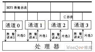
Figure 3 multi-channel working principle diagram
4 system software design
The system software includes three parts: operating system, driver and player application.
4.1 Implementation of the operating system
In an embedded system, there is usually no firmware like a BIOS, so the entire system's load-start task is completely done by the BootLoader. The task of BootLoader is to initialize the chip and the motherboard. The U-Boot-1.1.2 startup program is used because U-Boot has the advantage of supporting multiple systems and multiple platforms. Since the S3C44B0X does not have a storage management unit (MMU), the standard Linux kernel cannot be ported, and μClinux is mainly designed for an operating system without a MMU [4], so it can be ported as a player operating system platform. The development board files that need to be created during the migration process can be implemented by modifying the corresponding configuration files and drivers.
4.2 Driver Design
The μClinux kernel compiled by this system includes drivers such as USB and LCD, which can be applied as needed. But for the MP3 decoding part of the chip driver needs to write their own. The main functions of the audio driver implementation are: (1) the initialization of the chip can be completed when the system is started; (2) the appropriate software interface can be provided to the operating system during the specific operation. The audio driver initialization procedure is as follows:
Void STA013_Init(void)
{
If(STA013_SendCommand(RESET_REG,0,0x00)) //Reset STA013
STA013_PrintError();
If(STA013_SendCommand(ACT_CON_REG,0,0x00)) //Inactive state
STA013_PrintError();
If(STA013_SendCommand(PWR_CON_REG,0,0x00)) //Power on
STA013_PrintError();
If(STA013_SendCommand(FS_CON_REG,0,
I STA013L_FsValue[SysInfo.SamplingIndex])) / / select the sampling frequency
STA013_PrintError();
If(STA013_SendCommand(IF_CON_REG,0,0x02+(0<<6))) //Select 16-bit IIS data format
STA013_PrintError();
If(STA013_SendCommand(ANG_CTL_REG,0,0)) // 0x13, 0x12 select DAC
STA013_PrintError(); and Line In input mode
If(STA013_SendCommand(DGT_CTL_REG,0,0x00)) // DAC mute
STA013_PrintError();
If(STA013_SendCommand(LHP_VOL_REG,0,0x00)) //left channel volume
STA013_PrintError();
If(STA013_SendCommand(RHP_VOL_REG,0,0x00)) //Right channel volume
STA013_PrintError();
If(STA013_SendCommand(ACT_CON_REG,0,0x00)) //Data transfer activation
STA013_PrintError();
}
4.3 Design of the player
As a major innovation of this system, it is very important to design a reasonable and efficient playback program code in the multi-channel part. Here, the MP3 file to be decoded is first copied from the USB device to the memory buffer, and then buffered. The method of sending to the decoder. During playback, the program copies the MP3 file stream from the USB device to the corresponding buffer based on the song information for each channel. The main implementation code is as follows:
For(i=0;i<4;i++){
If((dbuf[i]=malloc(BUF_LEN))==NULL){
Printf("Allocation %d Error ", i);
Exit(1);
}
}
4.4 Implementation of the operation interface
A complete MP3 player device requires a simple operator interface. The operation interface of the system is selected by MiniGUI software. Through the selection of MiniGUI operation mode, the transplantation of MiniGUI [5] and the preparation of interface program, the final operation interface is shown in Figure 4. The whole operation interface is simple and clear. The system provides the current time, as well as the play, set and reset buttons. It can directly realize the multi-channel playback function through the play button, and arrange the song directory through the setting button.

Figure 4 player main interface
5 Conclusion
Compared with traditional MP3 players, multi-channel MP3 players have many advantages to meet the higher performance requirements of background music in large public places. The multi-channel MP3 player can realize simultaneous playback of multiple audio output channels, and can realize large-capacity storage of songs through a USB interface external storage device. In addition, the system also provides a series of interfaces such as serial port and Ethernet to facilitate data exchange and software upgrade with the outside.
This paper innovates: Designed a multi-channel MP3 player based on ARM7 platform, which realizes multi-channel synchronous playback of mp3 files on external mobile hard disk or U disk.
references:
[1]. S3C44B0X datasheet http://
[2]. STA013 datasheet http://
[3]. AK4393 datasheet http://
[4]. SL811HS datasheet http://
[5]. ISP1520 datasheet http://
[6]. CD4066 datasheet http://
:
Rubber Binder,Rubber Adhesives,T45 Rubber Binder
Foshan Lanxun Trading Co., Ltd. , http://www.chpigmentpaste.com