The vehicle drive anti-skid control system improves the traction and steering stability of the vehicle on the weakly attached road surface by controlling the driving wheel slip state. The essence of the development of the vehicle electronic control system is the performance matching between the vehicle control prototype and the actuator, but the computer simulation is difficult. Complete this task. With the maturity of related technologies, hardware-in-the-loop simulation is becoming the main research method for the development of automotive electronic control systems with its short development cycle, low cost and close to the actual situation [4-5].
With the continuous improvement of the performance of microcomputers, it is feasible to realize real-time simulation by means of PC. Matlab/Simulink is widely used as a commonly used modeling and simulation software. Based on this graphical language, MathWorks has introduced the Real-Time Workshop (RTW) toolbox to turn graphical languages ​​into executable code languages ​​for real-time simulation. xPC Target (xPC target) is a real-time simulation system construction path for RTW architecture, and supports multiple types of I/O devices (including PCI and ISA and RS232, etc.), which can easily build hardware embedded real-time systems. Rapid prototyping and hardware-in-the-loop simulation and testing of control systems or systems.
Based on the Matlab/Simulink software platform, the hardware-in-the-loop simulation platform for vehicle drive anti-skid control is established. The hardware-in-the-loop simulation experiment of the controller is carried out through the platform. The experimental results show that the controller can work stably, and the control algorithm can effectively control the slip of the drive wheel, significantly improve the starting acceleration performance of the vehicle, and lay a foundation for the actual vehicle test and the further development of the electronic control unit.
1 Vehicle dynamics simulation model The vehicle drive anti-skid control is the control of the longitudinal force of the car. The longitudinal force of the car is divided into the driving force and the braking force. The driving force is transmitted by the engine to the wheel through the transmission system. The braking force is made by the system. Dynamic torque generated. In the research of driving slip control, the driving force is controlled, so the mathematical model of the vehicle system must be established, which is the basis for the research of longitudinal force control. This paper mainly establishes vehicle system dynamics simulation model including engine model, powertrain model, tire model and vehicle model.
1.1 Engine model Since the driver can control only the throttle opening of the engine during the running of the car, the established engine model mainly refers to the certain throttle opening and the engine output torque under the engine speed.
Through the collation test, a discrete array of engine steady-state torques and their corresponding throttle opening arrays and engine speed arrays, that is, engine external characteristics and partial load characteristics, are obtained for calculating the real-time output torque of the engine in the engine model. Figure 1 is a partial load characteristic diagram of the test vehicle engine. These data are used to calculate the engine real-time output torque in the engine model. 
This article refers to the address: http://
In the calculation, firstly, according to the throttle opening degree at this time, a two-dimensional interpolation function is used to obtain a corresponding set of engine partial load characteristic torque arrays, and then the partial load characteristics obtained by the two-dimensional interpolation function are obtained according to the engine speed at this time. The torque array is interpolated to obtain the net output torque of the engine at this time. It can be expressed as the output net torque corresponding to the engine speed under a certain throttle opening a. 
1.2 Nonlinear tire models The tire models currently used come in many forms, and the magic formula is one of them. The model uses the combination formula of trigonometric functions to fit the tire test data. The longitudinal force Ftx, the lateral force Fty, the positive moment Ftz, the turning moment Mtx, the resistance moment Mty and the tire can be completely expressed in the same formula. The combined action of longitudinal force and lateral force is called the “magic formulaâ€. Its general expression is: 
Where Y(x) can be a longitudinal force or a lateral force or a positive moment. The independent variable can represent the yaw angle or the longitudinal slip ratio of the tire in different cases, respectively. The coefficients B and C in the formula , D and E are in turn determined by the vertical load and camber angle of the tire.
The magic formula tire model established in this paper mainly describes the relationship between the longitudinal force, the lateral force and the positive moment of the tire, respectively, the tire side angle, the wheel slip ratio and the tire's normal reaction force. The relationship between the variables is as follows. Figure 2 shows. In the figure, α is the side angle, λ is the longitudinal slip ratio, γ is the tire camber angle, Fz is the tire vertical load, and a, b, and c are the calculation parameters, which generally need to be tested. 
1.3 Vehicle Model The vehicle dynamics model is a mathematical description of the motion state of the vehicle body in space, which can more accurately give the dynamic response of the vehicle under external force in space. The paper establishes a simulation model of the 7-DOF vehicle-driven anti-skid control system, including three movements of the longitudinal, lateral and yaw of the vehicle body, and the rotation of the four wheels around the axle. The differential equations for each degree of freedom are as follows: 
Where Fx and Fy are the total components of the longitudinal and lateral forces of the tire in the vehicle coordinate system, Mz is the vehicle yaw moment, p is the roll angular velocity, ωr is the yaw rate, u is the longitudinal speed of the vehicle, and v is the vehicle side. To the speed, φ is the rollover angle, ωi is the wheel speed, Mdi is the drive torque, m is the vehicle mass, Izz is the yaw yaw of the vehicle around the z axis, Ixxs is the vehicle's yaw moment around the x axis, h' is The distance from the center of mass of the sprung to the axis of the rollover, ms is the sprung mass, Cφ is the rollover damping, Kφ is the rollover stiffness, Cd is the air resistance coefficient, Ïa is the air density, and Af is the forward projected area.
Ax and ayu are the components of the vehicle's centroid absolute acceleration in the X and Y directions of the vehicle coordinate system:

The calculation of other variables such as vertical load, vehicle longitudinal force, lateral force and yaw moment are described in [5] and will not be described in detail here.
2 drive anti-skid control system design
2.1 The electronic control unit design system uses Freescale's 16-bit single-chip MC-9S12DT128 as the central processing unit. The microcontroller core is an HCS12 structure. A lot of resources are integrated on-chip, including 128KB FLASH ROM; 12KB RAM; 4KB EEPROM; 8-channel Pulse Width Modulation Module (PWM); 8-channel Enhanced Capture Timer Module (ECT); 2 8-channel AD conversion module (ATD), etc. The chip has a powerful timer function and is ideal for the design of electronic control units for vehicle chassis. In the CODEWARRIOR integrated development environment, you can compile, download and debug the program.
The ECU circuit mainly includes: a power module (+12V to +5V), a wheel speed signal processing module, a minimum system module, a solenoid valve driving circuit, an alarm light indicating circuit, and the like. The entire controller structure is shown in Figure 3. The wheel speed signal has four paths, each from four wheels. The wheel speed measurement uses a magnetoelectric sensor, and the output is a sine wave with varying frequency and amplitude. The frequency is proportional to the measured wheel speed. This analog signal is not easily read by the ECU and needs to be filtered, amplified and shaped. 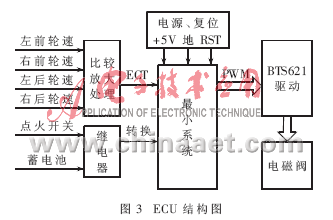
2.2 Drive Slip Control Program Design The main flow of the ASR control program is shown in Figure 4. The block in the figure is the subroutine module, and all of them are automatically returned to the main program.

For a uniform road surface, the driving wheel slip rate is the main threshold, and the wheel acceleration is the auxiliary threshold control strategy. The goal is to maximize the ground adhesion of the vehicle during an accelerated start. The separation road control logic uses the wheel wheel speed difference and wheel acceleration on both sides as the control threshold. For the two-wheel drive condition, the non-driven wheel speed average can be used as the actual vehicle speed; the left and right drive wheel speeds are judged, and the high-speed wheels are selected for control. In addition, when the driver depresses the brake pedal, the ASR system should immediately exit the control, which is not discussed here.
2.3 Hardware-in-the-loop simulation platform The hardware-in-the-loop simulation test bench consists of a microcomputer (host and target), a signal generation board, a data acquisition card, a solenoid valve and an electronic control unit. The simulation mode uses the xPC target structure, as shown in Figure 5. . The xPC target is a complementary product based on the RTW (Real-Time Workshop) architecture provided and distributed by MathWorks, which transforms an Intel 80x86/Pentium computer or PC compatible into a real-time system and supports many types of I/O. Interface board. It uses a "dual-machine" solution for the host and target, using two PCs. The host is used to run Simulink with a target code compiler. The target machine is used to execute the code generated in real time. The target machine runs a highly compact real-time operating kernel that communicates between the host and the target via an Ethernet connection. After the simulation is completed, the result data can be uploaded to the host for analysis and processing. 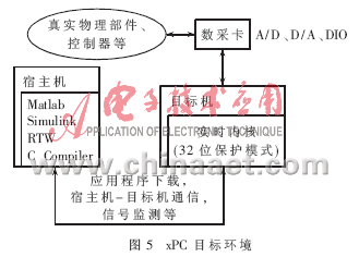
The vehicle dynamics model is built in the Matlab/Simulink environment of the host PC, and then the model is automatically converted into C code by using the xPC tool, and downloaded into the industrial computer through the Ethernet as the controlled object to realize real-time simulation.
The real physical components are mainly the electronic control unit designed. The signal reception and conversion of the hardware part and the vehicle model are completed using Advantech's high-speed data acquisition card PCL-726.
3 Simulation According to the above method, the ASR hardware-in-the-loop simulation platform is constructed, and the designed electronic control unit is embedded, and a certain working condition is set to carry out the semi-physical simulation research on the driving anti-skid control of the rear-wheel drive vehicle. Some of the simulation parameters are as follows: the whole vehicle mass is 130kg, the sprung mass is 117kg, the whole vehicle is around the Z-axis yaw inertia of 1500kg·m2, the wheel radius is 0.295m, the tire moment of inertia is 1.8kg·m2, and the whole vehicle is around the X-axis side turning inertia of 750kg· M2.
The initial vehicle speed and the wheel speed are zero, starting with a certain throttle opening, setting the adhesion coefficient of the low attached road surface to 0.1, and the adhesion coefficient of the high attached road surface to 0.7. This paper gives the simulation results of the right drive wheel for analysis.
3.1 When the simulation of low-impedance road surface is simulated, the ASR control (without embedded controller) is not performed first. The adhesion coefficient is 0.1 uniform and the road surface is low. The vehicle starts from the first speed. The curve of wheel speed and vehicle speed is shown in Figure 6. Show. It can be seen from the figure that the rotational speed of the driving wheel rises rapidly, the vehicle speed hardly increases, and the acceleration performance of the vehicle is poor. 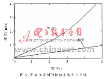
Embed the designed ECU in the simulation system, and apply control to the drive wheel. The goal is to control the slip rate of the drive wheel to be near the optimal slip rate. On the low-attach road with an adhesion coefficient of 0.1, the first speed is accelerated, and the simulation is started. The result is shown in Figure 7. It can be seen from the illustrated slip ratio and wheel speed curve that the control system can basically control the wheel slip rate near the optimal slip rate, and the wheel speed fluctuation is relatively small, so the acceleration performance and starting stability of the vehicle are obtained. Significant improvement. 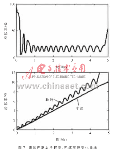
3.2 Separation of pavement simulation Separation of pavement is a typical road condition when the vehicle starts and accelerates. When the vehicle is simulated, the vehicle starts at the first step of the separation road (0.1/0.7). Figure 8 shows the variation of the wheel speed and the yaw rate of the vehicle. curve. It can be seen that the slip rate of the wheel with low adhesion is effectively controlled, and the wheel speed difference between the left and right drive wheels is also reduced. The yaw rate of the vehicle is also controlled within a small range, so that the vehicle is scheduled. The trajectory starts to accelerate.

Based on the xPC goal, the hardware-in-the-loop simulation platform of the vehicle drive anti-skid control system is established. The verification of the control algorithm and the debugging of the control parameters are completed. The preliminary verification of the matching performance of the control system software and hardware is realized, which lays a foundation for the real vehicle test. For the rapid development of the vehicle-driven anti-skid control system, sensors and hydraulic actuators can be further embedded in the loop, and the powerful functions of the xPC target and the Matlab platform enable low-cost rapid development.
High Quality Tablet Ram 4GB/8GB/16GB SODIMM UDIMM DDR4 8gb Laptop 2400mhz Ram
Model
DDR4 SODIMM
Brand
Semsotai /OEM /ODM /OBM
ECC
Non-ECC
Capacity
4GB/8GB/16GB
Chipsets
Samsung /SK Hynix/Mircon/Spec tek
Frequency
2133MHz/2400MHz/2666MHz/3200MHz
Speed
PC4-17000/PC4-19200/PC4-21300/PC4-25600
Componets Configuration
(256m/512m/1G) x8/x16
Memory CAS Lantency
CL15/CL17/CL19/CL21/CL22
Supply Voltage
1.2V
Pin Count
260PIN
PCB layer
8 /10 layer high speed PCB
Certificate
CE/FCC/ROHS
Operation temperature
0C-95C
Compability
100% Work with all motherboard
Ddr4 Laptop Memory,Ddr4 Rgb Ram,Ddr3 Ram 8Gb Pc 1600,Game Ddr3 8Gb
MICROBITS TECHNOLOGY LIMITED , https://www.microbitstrade.com