LED technology has achieved rapid development, and improvements in chip design and materials have led to the development of brighter, more durable light sources, and the range of light source applications is expanding. The increasing awareness of energy conservation has also accelerated the popularity of LED lighting technology. Today, LED lights are rapidly replacing traditional lighting methods with the following advantages: 1) low energy consumption, new lamp power consumption ranging from 0.83 watts to 7.3 watts; 2) long life, LED bulbs can be used for 50,000 hours; 3) LED bulbs Heat-resistant, shock-resistant, ready-to-use, ideal for applications requiring frequent switching operations; 4) Helps meet safety and green initiatives; 5) LED bulbs are not hot to the touch, contain no mercury; 6) Fully dimmable When dimming, the LED bulb will not change color, and the incandescent lamp will turn yellow when dimming; 7) Ballast resistor without frequency interference, which will not interfere with radio and TV signals.
Although this technology is becoming more and more popular, LED lighting manufacturers continue to overcome the problem of strong thermal sensitivity of LED light sources. Excessive heat or improper application can compromise the performance of LED light sources.
Thermal conductivity comparison
A luminaire using a 60W incandescent bulb produces approximately 900 lumens of illumination and must dissipate 3 watts of heat by conduction. Using a typical DC LED as the light source to achieve the same 900 lumens illumination requires only 12 LEDs. Assuming VF (forward voltage) is 3.2V and current is 350mA, the input power of the luminaire can be calculated as follows:
Power = 12 x 3.2V x 350mA = 13.4W.
In this case, about 20% of the input power is converted to light and 80% is converted to heat. Depending on a variety of factors, heat generation may be related to underlying irregularities as well as phonon emissions, seals, and materials.
Of the total heat generated by the LED, 90% is transmitted by conduction. To dissipate heat from the LED junction, conduction is the primary channel of heat conduction because convection and radiation account for only about 10% of the total heat transfer. For example, an LED may convert nearly 10.72 watts of heat (13.4 x 0.8). Among them, 9.648 watts (10.72 × 0.9) is transmitted or migrated from the LED junction by conduction.
Clearly, LED light sources require precise power and thermal management systems because most of the power supplied to the LEDs is converted to heat compared to other sources. This heat can affect LED life and color output without proper thermal management. At the same time, since LED drivers are silicon devices, they quickly fail. This means that a fail-safe backup overcurrent protection device must be provided.
Junction temperature effect
The optical performance of LEDs varies significantly depending on the temperature. The amount of LED luminescence decreases as the junction temperature increases. For some techniques, the emission wavelength also varies with temperature. If the drive current and junction temperature are not properly controlled, the LED efficiency will drop rapidly, resulting in reduced brightness and reduced lifetime.
Another LED characteristic associated with junction temperature is the forward voltage. If only a simple bias resistor is used to control the drive current, the VF will drop with increasing temperature and the drive current will increase. This can lead to thermal collapse, especially for high power LEDs, and component failure. A common practice is to control the junction temperature by mounting the LED on a metal core PCB to accelerate thermal conduction.
Wire-coupled transients and inrush currents also reduce LED life, and many LED drivers are susceptible to damage due to DC voltage and polarity errors. The output of the LED driver is also damaged or destroyed by a short circuit. Most LED drivers have built-in safety features, including thermal shutdown and LED open and short detection. However, to protect integrated circuits (ICs) and other sensitive electronic components, additional overcurrent protection devices may be required.
LED driver input and output protection
The LED is driven by a constant current with a forward voltage of less than 2V to 4.5V, depending on color and current. Old-fashioned designs rely on simple resistors to limit LED drive current, but designing LED circuits based on typical forward voltage drops specified by the manufacturer can cause LED drivers to overheat.
This can happen when the forward voltage drop across the LED drops to a level well below the typical specified value. In such events, an increase in voltage through the LED driver may result in higher total power dissipation from the driver package and thus adversely affect performance or lifetime.
Currently, most LED applications use power conversion and control devices to connect various power sources, such as AC lines, solar panels, or batteries, to control the power dissipation of the LED driver. These interfaces are protected against damage due to overcurrent and overtemperature, and polymer positive temperature coefficient (PPTC) devices with resettable capability are often used. A PolySwitch LVR device can be placed in series with the power input to prevent damage due to electrical shorts, circuit overload, or user misuse. In addition, the metal oxide varistor (MOV) placed on the input also contributes to overvoltage protection within the LED module.
The PolySwitch LVR can also be placed after the MOV. Many equipment manufacturers prefer protection circuits in combination with resettable PolySwitch devices with upstream fail-safe protection. In this example, R1 is a ballast resistor used in combination with a protection circuit.
The LED driver is easily damaged by DC voltage and polarity errors. The output can also be damaged or destroyed by a harmful short circuit. Charged ports are also susceptible to damage due to overvoltage transients, including ESD pulses.

Figure shows a synergistic protection scheme for input and output of LED drivers.
The figure above shows a typical circuit protection design for LED drivers and bulb arrays. The PolyZen device on the driver input provides designers with the simplicity of traditional clamping diodes while avoiding the need for large amounts of heat (slices). The device facilitates transient suppression, reverse bias protection, and overcurrent protection in a single, small package.
The PolySwitch device on the drive output helps prevent damage from unwanted short circuits or other load anomalies. In order to fully utilize the role of the PolySwitch device, it can be thermally connected to a metal core circuit board or LED heat sink. In addition, PESD devices that are collocated with LEDs can also protect against electrostatic discharge (ESD).
Meet the safety standards of Class 2 power sources
The use of Class 2 power sources in lighting systems can be an important factor in reducing costs and increasing flexibility. An inherently limited power source (a transformer, power supply, or battery) can contain protection devices as long as they do not rely on them to limit the output of Class 2 power supplies. An intrinsic limited power source, by definition, has a discrete protection device that automatically interrupts the output when the current and energy outputs reach a predetermined value. Various circuit protection devices help to provide safe operation of Class 2 power sources for LED lighting applications.
to sum up
Resettable PPTC devices prevent damage due to overcurrent and overtemperature faults in LED lighting applications. MOV overvoltage protection devices help manufacturers meet the requirements of various safety mechanisms, provide high current delivery and energy absorption, and respond quickly to overvoltage transients.
Compared to most ESD protection devices, PESD devices have extremely low capacitance (0.25pF) and have the most common form factor in the electronics industry. PolyZen devices offer designers the simplicity of traditional clamp diodes while avoiding the need for large amounts of heat dissipation. This single-device solution provides protection against damage caused by improper power usage, transient immunity, reverse bias protection, and protection from overcurrent events.
Using these devices in a collaborative protection scheme allows designers to reduce component count, provide safe and reliable products, meet regulatory requirements, and reduce warranty and repair costs.
Remarks: Explanation of terms
VF---through the forward voltage drop of the LED. When conduction begins, the VF is approximately 2V (for red LEDs) and 3.5V (for blue LEDs).
Tj---LED internal temperature, on the PN junction. If the temperature is too high, the LED will be damaged.
IF---the forward current through the LED.
The Advantages of Lithium-ion battery pack
1.Higher energy density
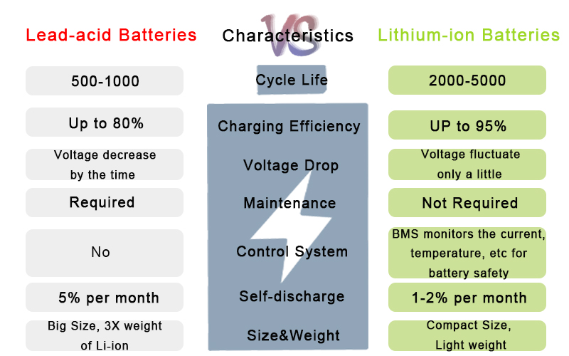
The higher energy density of lithium-ion battery pack means we are going to get more power out of the same physical size cell than we could get from a lead-acid battery. So when using lithium-ion battery for electronic gear, it means more runtime but less weight.2.Less weight
Less weight could be a big advantage for most electronic applications that need to be in a compact size and lightweight for use, including mobile applications, robots, drones, floor scrubbers, RVs. A lot of power is used for those devices, so less weight would be certainly an advantage for mobile applications.3.Thousands VS hundreds of cycles
More cycles are an advantage by a lithium product we`re gonna get. You know the lithium batteries could provide thousands of cycles versus lead-acid batteries which only offer hundreds of cycles. It is a big difference in the cycling ability of lithium over lead-acid batteries.4.Charge and discharge rate
We are able to discharge a lithium product much quicker than that of a lead-acid product and get the same capacity. If the lithium-ion battery pack is discharged to 80%, you can still get a good lifespan. But doing that with a lead-acid battery will damage its lifespan. Generally, a lead-acid battery can only use fifty percent of the discharge. The recharge time is quicker on a lithium product as well especially if we have a charger that`s large enough to put the capacity back. The lithium-ion battery packs have a low self-discharge rate of only 1-2% per month.
5. Less Maintenance
When using lead-acid batteries for power supply, regular maintenance is essential to ensure the battery performance. However, when purchasing lithium-ion batteries for power use, less maintenance is required. The lithium-ion cells is more stable with good performance. It saves a lot of time for maintenance and cost for replacement.

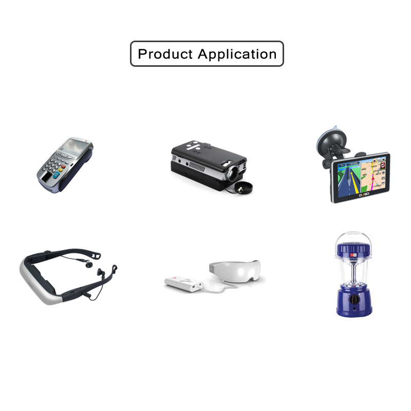
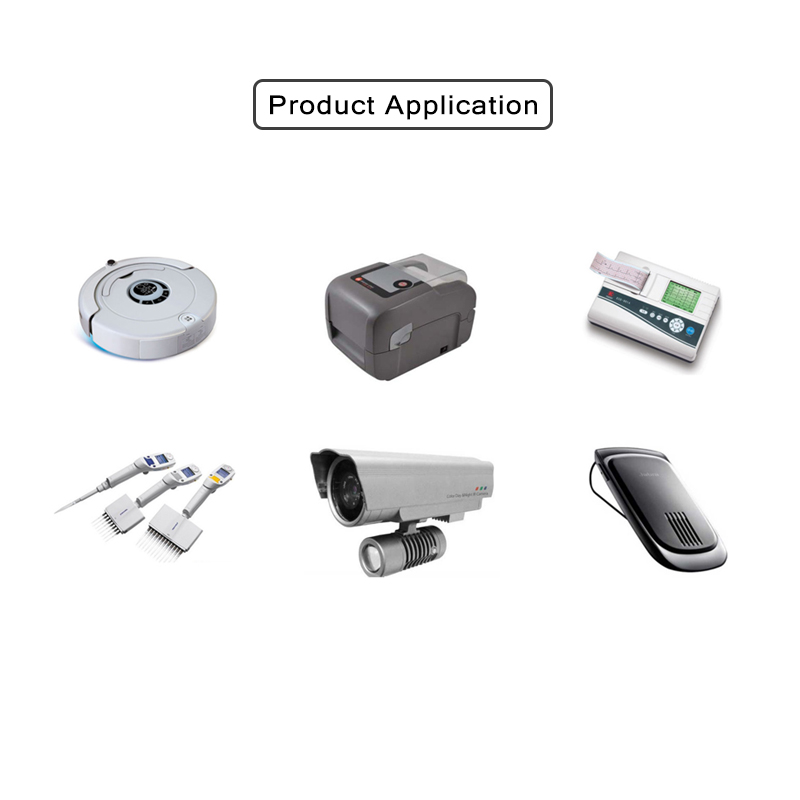
Lithium-ion battery pack Application


Lithium-Ion Battery Pack,Lithium Ion Battery For Solar,Smart Lithium Ion Battery Pack,Lithium Battery Pack
ShenZhen UFO Power Technology Co., Ltd. , https://www.ufobattery.com