The remote access control (RKE) system has been favored by users. More than 80% of North American cars and more than 70% of European cars are equipped with RKE systems. In addition to the obvious convenience, RKE's technology for turning on car brakes has an anti-theft effect. European car manufacturers cooperate with insurance companies to install RKE systems when they purchase auto insurance. Germany has begun to implement this policy and is expected to expand throughout Europe within a few years.
This article refers to the address: http://
Most RKE systems use one-way (simplex) communication, but the second- and third-generation RKE systems will provide a reverse-communication duplex operation that returns to the key, which can notify the owner of the need to refuel or need to increase the left front tire pressure.
The RKE system includes a wireless transmitter in a key fob (or key) that sends a series of short pulse sub-signals to a receiver mounted in the vehicle, the signal is decoded, the transmission is controlled by the receiver, and the door or baggage is opened or closed. box. In the United States and Japan, the wireless carrier frequency is 315 MHz, and in Europe, 433.92 MHz (ISM band). Japan's RKE system uses frequency shift keying FSK modulation, and most other countries use amplitude shift keying ASK modulation, whose carrier amplitude is modulated at two levels. In order to reduce the power consumption, the low level is usually close to 0, thus generating an on-off keying (OOK) modulation.
RKE system description and design goals
A typical RKE system (Figure 1) is a microcontroller mounted on a key fob or key. For a car, pressing a button on the control unit will wake up the microcontroller. The microcontroller sends a string of 64-bit or 128-bit data streams to the RF transmitter of the key, which is modulated by the carrier and uses a simple ring-shaped printed circuit board antenna (although the efficiency is not high, the loop antenna can be placed on the PCB. Low cost, widely used) radiated out and implemented unlocking operation.
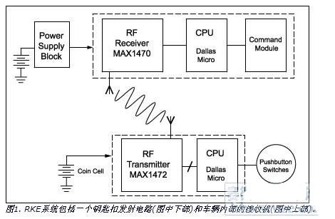
In a vehicle, the RF receiver captures the transmitted data and passes it directly to another microcontroller to complete the decoding and issue the correct control information to start the engine or open the door. The key controller with multiple buttons can also choose to open the driver's door, all doors or luggage.
The data stream is transmitted at a rate of 2.4 kbps to 20 kbps and is usually composed of the following fields: preamble, opcode, check digit and "rolling code". The rolling code will modify its own value after each use to ensure the safety of the vehicle. If there is no rolling code, the transmitted signal may accidentally turn on another vehicle, or steal the thief due to the transmission code, and then use it to turn on the vehicle.
There are several main goals that govern the design of the RKE system. As with all mass-produced automotive parts, they must be low cost and highly reliable. Both the transmitter and the receiver should consume minimal power, because replacing the battery of the key controller is very cumbersome and charging the car battery is more complicated. On the one hand, RKE system designers should pay attention to these requirements. On the other hand, they must ensure certain receiving sensitivity, carrier tolerance and other technical parameters to achieve the maximum transmission range while meeting low cost and small current limit.
Other restrictions include: local regulations governing proximity communication equipment, such as the US FCC regulations. Near field communication equipment does not require a license, but the product itself is subject to different laws and regulations of each country. For the United States, the relevant management document is the Federal Government Regulations (CFR), Part 15 of Title 47, which covers the 260MHz to 470MHz band (15.231) and the 902MHz to 928MHz band (15.249)
The following sections provide some restrictions on the RKE design of the FCC standard.
In accordance with Section 15.231, the device is allowed to transmit command or control signals, ID codes, to allow wireless control signals to be transmitted in an emergency, but not audio or image signals, toy control signals, or continuous data.
The transmission time cannot exceed 5 seconds; only when the repeated transmission frequency is lower than once per hour, the fixed interval can be allowed to last for 1 second (longest).
The maximum field strength within three meters of the transmitting antenna is within 3750μV/m to 12500μV/m, and the linearity is proportional to the fundamental frequency (260 to 470MHz).
The frequency offset of 20 dB in the frequency band does not exceed 0.25% of the center frequency; the spurious radiation should be attenuated by 20 dB than the gain of the fundamental frequency signal.
The following sections discuss in detail the issues associated with RKE system design, starting with the generation of carrier frequencies.
Carrier generator
The first generation RKE circuit used a surface acoustic wave (SAW) device to generate the RF carrier of the transmitter and the local oscillator (LO) of the receiver. Unfortunately, SAW devices have an initial frequency uncertainty of at least ±100 kHz and their frequency stability is relatively poor with temperature. At the receiving end, if the IF passband is too wide, excessive noise is received when receiving the carrier, thereby limiting the distance the car responds to the key control signal.
A current alternative to SAW devices is to choose a crystal-based phase-locked loop (PLL). The use of PLLs is primarily due to increasingly stringent RF radiation regulations, especially in Europe and Japan. A transmitter using a crystal oscillator PLL is slightly more expensive than a transmitter using a SAW resonator, but the accuracy is generally increased by a factor of ten. Therefore, the receiver has a narrow IF bandwidth, and the transmission distance can be increased due to an increase in SNR.
Early SAW devices were designed to operate at the midpoint of the 433 MHz band (433.05 MHz to 434.79 MHz) with a bandwidth of 1.74 MHz to ensure system reliability during process and temperature changes. Therefore, for applications with a nominal carrier frequency of 433 MHz, the current frequency is 433.92 MHz, so the PLL crystal must be selected based on this frequency.
Currently, both the transmit and receive chips have a built-in phase-locked loop that requires only an external crystal oscillator to generate an effective RKE signal (refer to the supplement: RKE IC). For example, Maxim's MAX1470 PLL includes a 64-way circuit and a low-end-implanted 10.7MHz IF circuit (the chip can operate at 433.92MHz, but at 315MHz, its image rejection is best). At the 315MHz operating frequency, the required crystal frequency is fXTAL = (fRF - 10.7) / 64 = 4.7547 (in MHz). The IC requires a crystal with an oscillating frequency of 315MHz and a 5pF capacitor on the XTAL1 and XTAL2 pins. For crystal frequency adjustment, please refer to application note 1017: How to Select a Quartz Crystal Oscillator for the MAX1470 Superheterodyne Receiver.
Save power
Since the battery life is very important, the RKE system uses a variety of techniques to reduce operating current and "boot time." The voltage controlled oscillator (VCO) of the receiver PLL is an example of this design detail. The receiver needs to maintain an almost uninterrupted detection state to avoid leaking commands to turn on the vehicle; and to place it as much as possible in order to save power Shutdown state, even within a short interval between checks.
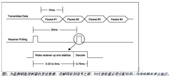
The controller's transmitting device typically continuously transmits 4 sets of 10ms data streams (about 40ms in total) to ensure that the receiver captures at least one of them. The receiver can perform a query operation every 20ms in an effort to capture at least two sets of data so that there is enough margin to eliminate timing errors and noise. The decoding time takes about 0.75ms (enough to receive 7 or 8 bits of data) to determine if it is valid data.
In addition to the decoding time, the polling operation must first have the receiver "wake up" and settling time. Most amplifier circuits can wake up quickly, but the VCO crystal is an electromechanical component that requires a certain start-up time. Of course, it takes longer to stabilize at the required frequency. For traditional superheterodyne receivers, this time typically takes 2ms to 5ms. The MAX1470's VCO takes only 0.25ms from power-up to crystal-stabilized oscillation. Thus, it takes only 1 ms (0.75 ms decoding, 0.25 ms stabilization) to detect the transmitted signal by waking up every 20 ms (Fig. 2). The MAX1470, which wakes up quickly, operates at 3.3V instead of 5V, which is one of four or five factors that save energy and extend battery life (as opposed to traditional superheterodyne receivers).
Strictly speaking, RKE is a short-range communication technology, the transmission distance of active systems can reach 20m, and the communication distance of passive RKE systems is 1 to 2m, even for short-distance transmission, ensuring low power consumption and low cost design for RF Circuitry is also a challenge. For simplicity, the transmitter and receiver antennas consist of looped or rectangular printed conductors on the PCB and use a simple LC network to match the impedance of the antenna to the transmitter or receiver chip (see application note 1830: How To Tune and Antenna Match the MAX1470 Circuit).
Add a low noise amplifier (LNA)?
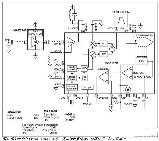
Due to the FCC regulations that must use low transmit power, small battery capacity, and uncertainty of the transmit antenna orientation, the RKE receiver chip is required to have extremely high sensitivity. One way to increase receive sensitivity is to add a low noise amplifier (Figure 3), but this approach reduces the dynamic range and may not be acceptable in a specific application. Consider the analysis of the MAX1470 superheterodyne receiver.
The receiving sensitivity depends on its noise figure, the minimum signal-to-noise ratio S/N required for carrier modulation detection, and the thermal noise of the system:
S = NF + n0 + S/N, Equation 1
Where S is the minimum signal level required, in dBm; NF is the noise figure of the receiver, in dBm; n0 is the thermal noise power of the receiver, in dBm; S/N is the signal The output signal-to-noise ratio of the detection, in dBm (usually based on an acceptable bit error rate).
For the sake of simplicity, for Manchester coded data, the S/N is estimated to be 5 dB. By definition, you can get:
N0 = 10log 10(kTB/1E-3),
Where k is the Boltzmann constant (1.38E-23), T is the temperature in degrees Kelvin; B is the system noise bandwidth, at room temperature (T = 290°K), at 1 Hz bandwidth, n0 = -174dbm/Hz. Relative to the 300kHz IF bandwidth, n0 = - 119dbm.
Assuming that the system sensitivity (S) is -109 dBm, the noise figure NF = 5 dB can be calculated using Equation 1. The relationship between the noise figure (NF) and the noise figure (F) is: (NF) dB = 10 logF, where F = 10 (NFdB/10). So, F = 3.162. For the case where multiple dual port components are cascaded, the noise figure is:
FTotal = F1 + (F2-1)/G1 + (F3-1)/(G1*G2) + . . . Equation 2
Equation 2 can be used to calculate the new noise factor when the external LNA is added to the system. For Maxim's MAX2640 LNA, NF = 1dB, gain = 15dB (ie, F1 = 1.26, G1 = 31.62). The noise factor of the original system is 3.162, so FTotal = 1.327, which is 1.23dB, is substituted into Equation 1:
S = 1.23 - 119 + 5 = -112.77dB.
Assume that the original sensitivity is -109dB, and after LNA, only 3.77dB is improved. Considering the effect of the third-order intercept point (IIP3) on the dynamic range, the MAX1470 has 16dB of internal LNA gain and -18dBm of internal mixer IIP3, while the total IIP3 is -34dBm. Add an external LNA with 15dB gain to reduce this number to -49dBm. Therefore, the addition of an external LNA has an approximately 4 dB improvement in sensitivity, but the system dynamic range is reduced by 15 dB! This tradeoff must be considered for a given application.
Direction of development
The next step in the development of the RKE system will involve two-way (half-duplex) communication, which is currently used in some high-end vehicles in the form of "passive RKE". When the driver approaches the car, the car launcher keeps polling to determine the driver's approach. Within a certain range (1 to 2 meters), the controller establishes two-way communication with the vehicle and opens the door. In addition to the confirmation function (confirmation that the door is locked), the current two-way system also includes a remote start function that allows the driver to start the engine at a distance.
Future developments may include tire pressure detection (TPS) technology, which, like passive RKE, is currently only used in certain trucks and luxury cars. The TPS system has many similarities with RKE. A controller similar to RKE is integrated with the pressure measuring and temperature measuring sensors and mounted on the seat of each tire. Each tire periodically sends a message to the in-vehicle receiver (similar to the RKE receiver) to provide the driver with an early warning of any tire problems. TPS and RKE have many similarities (close range, simple modulation, power saving, etc.), and future systems are likely to reduce costs by sharing and merging circuits.
RKE may evolve into a half-duplex system that informs the driver of the state of the car and whether it needs to be refueled before opening the door. If RKE proves to be durable and reliable, it will phase out the current key and the hardware associated with the door.
CMOS IC for RKE
Maxim is one of the few vendors that offer RKE products that can produce specific functions for integrated circuits in the RKE market. For the keychain controller, Maxim offers the industry's smallest 300MHz to 450MHz transmitter, the MAX1472, in a tiny 3mm x 3mm, 8-pin SOT23 package. Its 2.1V to 3.6V supply range allows the device to be powered from a single-cell Li-Ion battery and consumes only 5nA of supply current in standby mode.
When transmitting Manchester encoded data, the MAX1472 supports data rates up to 100kbps, consumes 3.0mA and 5.5mA supply current, and delivers -10dBm to +10dBm output power to 50Ω loads. The crystal-based phase-locked loop produces an accurate carrier frequency that allows the receiver to use a narrower IF bandwidth to increase the transmission distance. In order to reduce power consumption, the internal oscillator can be started up quickly. After the enable signal is issued, the startup time is only 220μs.
For the receiver on the car, consider using the MAX1473 super-heterodyne ASK receiver from 300MHz to 450MHz. The device has a high sensitivity of -114dBm and a fully differential mixer with 50dB of image rejection. The MAX1473 is optimized for operation at 315MHz or 433MHz. The chip uses a 3.3V or 5V supply, including a low noise amplifier (LNA), a fully differential image rejection mixer, a crystal-based PLL to provide a local oscillator, and a 10.7MHz IF limiting amplifier with Received Signal Strength Indication (RSSI). . The internal data filter and data slicer provide data output. In addition, the receiver MAX1470 can be selected. This chip is similar to the MAX1473 except that it is optimized for operation at 315MHz and operates from a 3.0V to 3.6V supply range.
Outdoor Power Supply(700W 1065Wh)
Outdoor power supply, also known as portable energy storage battery, is a device that uses high energy density lithium-ion battery pack as a means of energy storage to provide power supply for users when they are unable to access power. Outdoor power supply can provide power support for almost all electrical equipment. It has larger capacity, supports 220V AC output, USB fast charging output, vehicle cigarette lighter output port, DC output port, lighting flashlight, and even wireless charger and other functions, so as to provide users with more ways of power security as far as possible.
energy storage, power supply, lithium-ion battery, portable lithium battery, DC AC output
Wolong Electric Group Zhejiang Dengta Power Source Co.,Ltd , https://www.wldtbattery.com