0 Preface
At present, the communication, monitoring and data acquisition system of the power system adopts a distributed communication structure. With the application of new equipment and new technologies, there are three major problems in the communication, monitoring and data collection of terminal units in China's current power system: First, the distributed system has low efficiency; second, there are many types of terminals. And the communication protocols are not compatible with each other; the third is that the data acquisition front-end subsystem of the main station (the industrial control acquisition board, the protocol conversion board, etc.) has poor adaptability, and the actual use effect is unsatisfactory.
What the power system needs is such a main station data acquisition front-end subsystem: first, it should be able to communicate with multiple types of terminal units and data acquisition; second, it should be compatible with a variety of communication protocols; then, The most important thing is that it can intelligently and automatically complete the data acquisition and protocol conversion tasks for the terminal unit; finally, this subsystem should be cheap and good, and has good economy.
1 Acquisition and monitoring system structure
In the microcomputer monitoring application system of the substation and the industrial site, many remote field data points are collected. At this time, the main station PC and the lower computer complete the transmission of the command and the field collection data through serial communication. At present, it is more common to install data acquisition boards, such as A/D cards and 422 and 485 cards, in PCs or industrial computers. These data acquisition devices have the following defects: installation is troublesome, expensive; limited by the number of computer slots, addresses, and interrupt resources, and poor scalability; in some electromagnetic interference test sites, electromagnetic shielding cannot be specifically performed, resulting in acquisition The data is distorted. Universal Serial Bus (USB) is a new type of serial communication standard developed by Compaq, Microsoft, IBM, NEC and other companies in 1995 to solve the problem of traditional bus. The bus interface has the advantages of convenient installation, high bandwidth, and easy expansion, and has gradually become a development trend of modern data transmission. The USB-based data acquisition system makes full use of the above advantages of the USB bus, effectively solving the shortcomings of the traditional data acquisition system. This design combines RS-232 and RS-485 with USB with short transmission distance but high speed, reliable and easy to expand, forming a long-distance data acquisition system capable of multiple points, fast, reliable and low cost.
Acquisition and monitoring system structure
2 adapter hardware circuit implementation
The communication adapter hardware structure is as shown in Figure 1. The microcontroller adopts AT89C52, which has the characteristics of fast operation speed and compatibility with MCS51 instruction set. It integrates 8Kflash internally and is cost-effective. An external watchdog circuit, the MAX706, provides reliable protection for the microcontroller. In order to prevent the influence of external interference on the MCU, the interface between the MCU and the lower computer is isolated by optocoupler. The isolation of the control interface is TLP521-2, and the RXD and TXD are 6N137 isolated.
The USB interface adopts PHILIPS USB control chip PDIUSBD12. The control chip can realize the bus interface function of the parallel bus to the USB port of the microcontroller, and the programming is convenient. It is suitable for various microcontrollers, and the PLL and SIE integrated with USB function are integrated. The FIFO module can be used with a common microcontroller to implement a fully functional USB peripheral. For a microcontroller, the PDIUSBD12 acts like a memory device with an 8-bit data bus and an address bit (two locations). The connection to the USB is achieved by setting D+ (for high-speed USB devices) high with a 1.5kΩ pull-up resistor. The 1.5kΩ pull-up resistor is integrated inside the PDIUSBD12 and is not connected to VCC by default. The establishment of the connection is accomplished by issuing commands from an external/system microcontroller. This allows the system microcontroller to complete the initialization sequence before deciding to establish a connection with the USB. The USB bus connection can be reinitialized without the need to unplug the cable.
Considering that the bus commonly used in the industrial field has RS232, RS485, etc., MAXIM and MAX485 receivers of MAXIM are used to achieve level conversion. The interface with the outside world adopts photoelectric switch, and the bus type is selected by the host computer to select the interface mode with the outside world, thereby effectively avoiding the inconsistency between the set value and the actual operation. Because the RS-485 bus is a parallel two-wire interface, once a chip fails, the bus may be “pullâ€. Therefore, the two-line VA, VB and bus should be isolated. Usually, a 4~10Ω PTC resistor is connected in series between VA, VB and the bus, and a 5V TVS diode is connected across the ground to eliminate line surge interference. If there is no PTC resistor and TVS diode, it can be replaced by ordinary resistor and voltage regulator. At the same time, 0.1uf capacitor is externally connected to the chip, which can effectively prevent external interference.
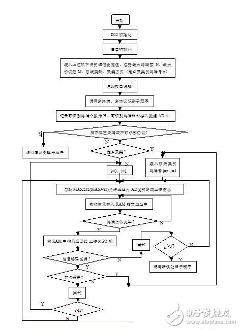
3 Adapter software design
The software of the adapter mainly includes the software of the AT89C52 microcontroller and the management software of the host computer. Taking into account the processing speed advantage of the host computer, the work of protocol conversion is completed by the client service program of the host computer. The single-chip AT89C52 mainly realizes intelligent terminal and protocol identification and communication and data transfer with the lower computer. Since the communication with the host computer by the USB interface does not occupy the CPU time of the host computer system, the host computer is freed from the communication bottleneck, and the speed advantage of the host computer is fully utilized.
Portable Heater Fan is ideal for use in an office or a small room. This heater is an automatic thermostat control with four positions for fan only, warm, hot, as well as off. The Heater Fan has a safety switch to shut off when tip over. It also has a thermal cut-off safety, a thermal fuse and a indicator light to let you know when it is working or not. This Fan Heater has two heat settings: 1000 and 2000 watts. When you just want to circulate some air, you can set it to cool fan only. or Keep warm when winter.
Portable Heater Fan, normal specialize as below:
- 2 heat settings (1000 and 2000 watts)
- Automatic thermostat control
- 4-position function switch (off, fan, warm and hot)
- Cooling Fan forced only setting
- Thermal fuse
- Thermal cut-off link
- Tip-over safety switch
- Power indicator light
Fenry have special portable fan heaters with 3 settings: 800W/1200W/2000W or 1200W/2400W with model number 809 series.
If you need, please contact us
thanks
Mainstays 2 In 1 Heater With Fan,Warmwave Space Heater,Portable Heater Blower,Portable Electric Fan Heater
Fenry manufacturing Co., Ltd , https://www.cnfenry.com