Among the full-bridge inverters, the filter inductor is a very important component, and the determination of the inductance value will directly affect the performance of the circuit. This article will introduce you to the calculation method of the filter inductor and the materials used in the inverter.
To determine the value of the filter inductor in the inverter, we first need to determine the LC value of the inductor, and then design on this basis.
In general, the inverter filter inductor uses Iron Powder material, or High Flux, Dura Flux material, and Ferrite. Generally, it should be guaranteed that there is a ratio of iron loss to copper loss, such as 0.2~0.4, the reason why it is not used 0.5 (the highest efficiency at this time) is because of heat dissipation.
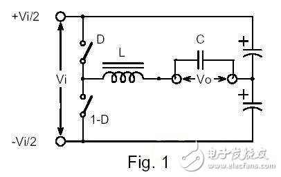
For the half-bridge inverter circuit shown in the above figure, since the output is a sine wave, according to the circuit principle, the SPWM wave has the highest duty ratio (0.5, excluding the dead time) when the output crosses zero point. The highest dB, the maximum ripple current is:
Ippmax=Vi/(4fL)(1)
f is the SPWM wave frequency and L is the filter inductance.
The corresponding B value is:
Bpkmax=10e8*Vi/(8fAN) (2)
A is the core cross section, N is the number of turns, the unit is in centimeters per second, and the magnetic density unit is Gauss. Substituting (1) into (2) gives:
Bpkmax=10e8IppL/(2AN)(3)
When the instantaneous value of the output voltage is not zero, the voltage on L can be obtained by subtracting the output voltage from the Bus voltage, and then the Bpk of each SPWM period can be obtained according to the frequency of the duty cycle, and the relationship with the output voltage is as follows:
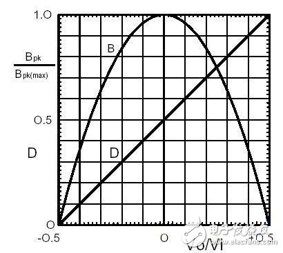
The highest ratio of Vo/Vi in the figure is 0.5, which is only for the case where the output peak is equal to the Bus voltage. In actual use, if higher output accuracy is required, the Bus will also decrease and the ratio will become smaller. It can also be seen that the higher the output voltage, the lower the magnetic density change. The above figure can help us to change the magnetic density in the ideal core, but it is not conducive to direct calculation of losses.
The figure below shows the ratio of average loss to maximum loss under different materials for different output voltage peaks. Of course, the loss occurs most when the output is zero.
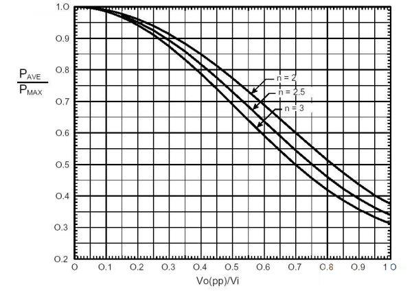
In actual design, only know the output voltage peak and the bus voltage. According to equation (2) or (3), Pmax can be known by the Steinmetz formula Pmax=k*Bpkmax*n*f*m, so that Pave, which is the iron loss of the inductor you designed, can be known.
As for the copper loss, I believe that it is simple, and multiply the DC resistance of the output current by the effective value of L. Ripple does not have to be considered, too much trouble. If the frequency is high enough, if there is eddy current, multiply a factor. However, the temperature coefficient has to be considered.
The n values ​​of some materials are given below to facilitate the search for curves:
Micrometals
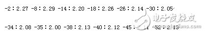
For other materials, manufacturers have to provide n values, or other similar parameters, and then count them.
Another point is that the optimal solution calculated by the control theory and the above method may not be consistent, and it has its own choice.
This paper mainly gives the calculation method of the filter inductor in the full-bridge inverter, and makes recommendations for the selection of the material of the filter inductor, which is of great help to the novice designer. I hope that after reading this article, you can learn the calculation method of the filter inductor in the inverter, and lay a solid foundation for your own design.
Phone Wireless Earphones,Sports Bluetooth Earphone,Best Cheap Wireless Earbuds,Wireless Earbuds For Android
Dongguang Vowsound Electronics Co., Ltd. , https://www.vowsound.com