Abstract: In response to the requirements of modern power supply frequency modulation and amplitude modulation, it is proposed to use the PIC16F873 to generate SPWM wave control IR2136 to trigger the IGBT to generate PWM wave to generate the standard sinusoidal waveform of the inverter, so as to realize the frequency conversion amplitude modulation. At the same time, the output of the inverter bridge is sampled and filtered by the AD module to realize PI closed-loop control of the system. The simulation analysis by SIMULINK component in MATLAB shows that the output voltage dynamic response speed of this scheme is fast, with good precision control and real-time performance, small waveform distortion and high reliability.
With the advancement of science and technology, power quality has increasingly become the basis for the normal and good work of various electrical equipment. An ongoing research topic in the field of power technology is to study the reliability and stability of power supplies as the lifeblood of the electronic information industry.
The inverter is the core part of the power supply, and its modulation technology largely determines the quality of the power supply output voltage. The most commonly used modulation technique today is sinusoidal pulse width modulation (SPWM). With the advent of microcontrollers and their widespread application, intelligent control methods have gradually replaced traditional discrete component circuit generation methods or dedicated chip generation methods. The advantage of the intelligent inverter power supply is that it can not only realize the output of the modulated signal, but also provide an interface for the monitoring, processing and display of the system data parameters. At the same time, it combines with modern computer technology to produce fault self-diagnosis and self-protection functions, which can improve the stability of the system.
Under the premise of fully considering the cost and stability requirements of industrial control, this design uses PIC microcontroller as the control core, and then assists related external circuits to form an inverter power supply control system with advantages such as stability and intelligence.
First, the specific circuit design
The single-phase bridge inverter circuit is shown in Figure 1. [1] Under the normal working condition of the circuit, the two pairs of switching tubes need two sets of driving pulses with opposite phases to control, so that VT1 and VT4 can be turned on and off at the same time, and VT2 and VT3 can be turned on and off at the same time. The input DC voltage is 220VAC, and the load of the inverter is R. When the switches VT1 and VT4 are turned on, and VT2 and VT3 are turned off, the current flows through VT1, R and VT4, and the polarity of the voltage on the load is left positive and right negative; When the switches VT1 and VT4 are turned off and VT2 and VT3 are turned on, current flows through VT2, R, and VT3, and the polarity of the voltage on the load is reversed, and the direct current is converted into alternating current. To change the output AC frequency, change the switching frequency of the two sets of switches, and then get the positive and negative half-cycle symmetrical AC square wave voltage. When the load is purely resistive, the load current and voltage waveforms are the same and the phase is the same. When the load is inductive, the current lags behind the voltage, and the waveforms are different. The output is a superposition of a single-phase inverter circuit equivalent to three phases of 120° difference, that is, a three-phase inverter, and the principle thereof will not be described again.
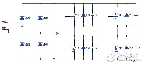
Figure 1 Single-phase bridge inverter circuit
Second, generate PWM wave chip selection
The design circuit is a single-phase full-bridge inverter circuit, and its main circuit is a typical DC-AC inverter circuit. The MC filtered signal is sampled by the single-chip microcomputer, and the obtained data is input to the PIC16F873 single-chip microcomputer. The data is processed by the PIC16F873 single-chip microcomputer chip, and the corresponding SPWM signal is output to the IR2136 driving circuit to control the switching circuit of the inverter circuit. In order to control the output of the inverter, adjust the operating temperature of the current monitoring system, and protect the control system circuit. There is also a keyboard, control frequency and amplitude, and a display module for displaying the working state of the system.
The PIC16F873 single-chip circuit is the control core circuit of this system. It mainly plays the following two functions: providing SPWM control signal for the drive circuit, controlling the on/off of the inverter bridge, and AD sampling the output voltage.
The main function of the integrated circuit IR2136 chip is to generate a corresponding trigger level to control the switching of the switching circuit of the inverter circuit, thereby controlling the output of the inverter. In addition, since the system outputs not only SPWM waves, but also low-order and high-order harmonics. This design uses an LC filter circuit to achieve the ultimate input standard sine wave.
Ω=2R/L is the cutoff angle frequency, R is the nominal impedance, and the cutoff frequency is fc, then there are:

Iseeled's Signal Splitter gives you the ability to plug in up to 8 dmx-out from one dmx-in. Led splitter is specially designed for connection of dmx receivers .Our dmx splitter can surmount the restriction that signle RS485 can only connect 32 sets of equipment. DMX splitter is an optical for DMX512 lighting. It's purpose is to allow the user more flexibility in connecting their DMX controller devices. Instead of having to make them all fit within a single daisy chain, each of the eight outputs from the Signal Splitter can be start of its own chain.
Photo show of Signal Splitter:

Signal Splitter
Signal Splitter,Led Signal Splitter,Dmx Signal Splitter,Signal Fiber Splitter
Shenzhen Iseeled Technology Co., Ltd. , https://www.iseeledlight.com