0 Preface
Lighting is an integral part of urban infrastructure. It plays an important role in the city's traffic safety, social security, people's life and cityscape. It also plays an irreplaceable role, and it also marks the strength and maturity of the city. More than 70% of the existing urban street lights use high-pressure sodium lamps, and their design life is 24 000 hours (5 years). However, due to large voltage fluctuations, fluctuations in many areas even exceed 15% of the rated voltage. Especially in the latter half of the night, due to the reduction of electrical load, the grid voltage sometimes approaches 245 V. The high voltage not only wastes energy but also shortens the bulb. Service life, in fact, the actual service life of urban street lights is now less than one year on average.
At present, there are two main ways to save energy at the power supply end. One is to use a midnight light, and the other is to use a voltage regulation method. And the night light is to save energy by turning off part of the lighting in the middle of the night. It has the characteristics of simple and easy operation. The disadvantage is that the road lighting is uneven, and it cannot solve the problem that the voltage in the middle of the night is high and affects the life of the light source. In indoor places such as shopping malls and schools. The method of reducing the supply voltage can not only save energy, but also prolong the life of the light source, which is a better energy-saving method.
To this end, this paper provides a design scheme of power-saving control system based on C8051F310 single-chip microcomputer. The system can control the output of the optimal lighting working voltage in real time according to the actual demand of the user site. Stabilize it within the allowable range, thereby improving power quality, saving lighting power and extending the service life of the bulb. It is very suitable for indoor and outdoor lighting power-saving control of street lamps, schools, shopping malls, etc.
1 basic design ideas
The street lamp controller designed in this paper adopts the form of autotransformer to adjust the voltage of the load street lamp. The primary and secondary side coils of the autotransformer not only have magnetic connection, but also electrical connection. Therefore, when the output voltage adjustment range is not large Its capacity is relatively small, so the material consumption is small, the cost is low, and the efficiency is high. The biggest advantage is that it overcomes the defects of the harmonic generation of the thyristor chopper type product, realizes the sine wave output of the voltage, and its structure and The functions are very simple and the reliability is relatively high.
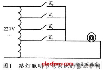
Figure 1 shows the basic block diagram of a street lighting power saving system. The basic design idea of ​​the street lamp power-saving controller is to close the four-contact switch with different ratios on the secondary side of the autotransformer, so that the voltage across the street lamp changes when the grid voltage changes (mainly the night grid voltage is high). Time) can be automatically stabilized at a preset value.
Fluorescent lamp is a kind of low-pressure discharge lamp that uses ultraviolet discharge to generate ultraviolet light to excite the phosphor layer to emit light. It is a main electric light source for factories, buildings, shopping malls, institutions, schools and home lighting. Table 1 shows the relationship between the illuminance, lifetime and voltage of a fluorescent lamp (the lifetime at rated voltage is 1).
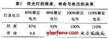
It can be seen from Table 1 that if the grid voltage is rated voltage 220 V, when the power is supplied with 90% rated voltage, the life of the lamp can be doubled and the illumination is attenuated by 7%. From human visuals, the perception of the change in light intensity by the human eye is calculated in a logarithmic relationship. The illuminance is attenuated by 7%, and the human vision can feel the light dimming by 1.6%. At this time, energy is saved by 19%. Achieve the best energy efficiency ratio. If the grid voltage exceeds 220 V, the energy saving rate is generally above 20%. Therefore, 90% of the rated voltage is the optimal operation and energy-saving voltage for indoor lighting power supply.
1.1 contact switch setting scheme
From the above analysis, 90% of the rated voltage is the optimal operation and energy-saving voltage of street lamps or indoor lighting, that is, 200 volts. China's power grid voltage standard is 220 V (-15% ~ +10%), that is, the grid voltage fluctuation range is 187 ~ 242 V. Assuming that the grid voltage fluctuates within the above voltage range, and the converter switching ratios of the autotransformer are a0, a1, a2, and a3 respectively, then the four voltage points of the grid fluctuation can be taken to calculate the change of the autotransformer. In order to make the grid voltage at these four points, the transformer output is 200V, these four points are 200V, 210V, 220V, 230V.
Set the bypass ratio to 1, that is, when the grid voltage is 200 V, the ratio of a0 is 1, then the ratio of the other switches is: a1=0.95, a2=0.90, a3=0. 87. Centering on these four points, we can divide the range of voltage fluctuations into four segments, as shown in Figure 2. Set the grid voltage to X, the output voltage to Y, and the ratio to ax.
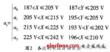
It can be seen from Fig. 2 that the accuracy of the output voltage value can reach at least 94.3%.
For winter, the time required to illuminate the road is from 17:00 to 6:00 the next day. According to the results of the voltage observation, the grid voltage should normally be stable at around 220 V, but in the middle of the night from 0:00 to 6:00 the next day, due to the small grid load, the grid voltage will gradually climb to 230 V. Based on this, the power saving rate can be calculated. The power consumption before voltage adjustment:
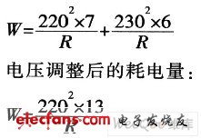
It can be seen from the calculation that the power saving rate can reach 21%.
1.2 Voltage Control Scheme
Let the input voltage be X, the output voltage be Y; the input voltage of the grid at time t is X(t), and the jump value of the contact switch is P. Then, the input voltage X can be judged to be in the rising phase or the falling phase by the following formula:

If the input voltage of a certain path at time t is greater than the input voltage at time (t-1), the input voltage is in the rising phase. Set the voltage jump value to P, that is, when the voltage rises to P+2. The contact switch jumps. On the other hand, if the input voltage at time t is less than the input voltage at time (t-1), the input voltage is in the falling phase. If the voltage jump value is set to P, that is, when the voltage drops to (P-2), The point switch jumps.
Among them, the 4 V hysteresis can be set so that the voltage has two different thresholds in the rising and falling stages. This hysteresis is set to ensure that the contact switch does not change frequently when the input voltage fluctuates frequently.
1.3 sampling plan
The variation of the grid voltage amplitude for the system is not very fast, and the requirements of the sampling speed and sampling accuracy of the street lamp controller are not necessarily high. The accuracy of the 10-bit AD converter that comes with the microcontroller C8051F310 can meet the system requirements. After the signal is converted by AD, the microprocessor calculates the effective value of the corresponding voltage and further judges. The design is simple in structure, low in cost, and sufficient for sampling speed and sampling accuracy.
The conversion accuracy of the A/D converter is determined by the combination of its reference voltage and output field length. The so-called conversion accuracy refers to the ability of an A/D converter to monitor the minimum voltage change. In fact, the conversion accuracy is the minimum step voltage of the A/D converter, which can be obtained by dividing the reference voltage of the MD converter by the number of conversion values ​​of the converter.
Since the C8051F330 uses 3.3 V as the reference voltage, its conversion accuracy is 3.3/1024, which is 3.22 mV, which can fully meet the accuracy requirements of this system.
1.4 Remote communication control scheme
Remote communication refers to the communication between multiple street lamp controllers and PCs. It is convenient for users to monitor the status of the street lamp controllers distributed everywhere. The system communicates with the serial port of the PC through the C8051F310's own UART port. The various status information detected is transmitted to the upper computer (such as the voltage of the power grid, the currents of the A, B, and C phases, and the various states of the street light controller, etc.), and the user can according to the upper computer The software selects the street light controller to be monitored and then issues various control commands based on its status, such as bypass or selecting the gear position in which the energy is saved.
In view of the fact that a PC is used for multiple street lamp controllers, a listening mode can be used to specify its communication protocol, that is, each controller is assigned a communication address. Before the communication starts, the host first sends the communication address, each controller receives the address, and then compares with its own address, the address matching street lamp controller starts to communicate with the host, and the other keeps listening state. This allows the user to easily monitor any controller.
Considering the transmission distance and anti-interference ability of the bus, the design adopts the RS-485 interface on the control board and transmits the signal in differential mode, so its ability to resist common mode interference is very strong.
- 6 Way Power Strip Extension with surge protector will protect your electrical devices from voltage spikes e.g. electrical surge or lightning. USB Ports Electric Socket 6 Outlet Extension provide you multi capability for various electronics power needs at the same time.
- Qualified Power Strip 6-Outlet Power Cord allowing you extend the outlet 6 feet (2 meters) away from the wall or even further.
- 6 Gang Power Strip is capable of overload protection, optional USB Charging Ports and surge protection, flexible design.
6 Gang Power Strip
6 Gang Power Strip, Smart Power Bar, 6 Way Power Strip Extension, Power Strip 6-Outlet, USB Ports Electric Socket 6 Outlet Extension
ZhongShan JITONGLONG Plastic Hardware Co. Ltd. , https://www.toukoo-electronics.com