Today's flat-panel digital TVs and displays are much thinner than older, bulky cathode ray tube (CRT) displays used in the past. These new flat-panel TVs are very attractive to consumers because they take up less space.
To help meet consumer demand and make such digital devices thinner, some vendors have turned to LLC resonant half-bridge converters to provide driving for the light-emitting diode (LED) backlights of these devices. This is because the zero voltage soft switching (ZVS) achieved with this topology results in a more efficient high power density design and requires fewer heat sink components than hard switching topologies.
One problem with this type of topology design is that the LLCdc/dc transfer function changes significantly with load changes. However, this makes it more complicated to set up the LLC controller and compensate for the current loop in the LED driver. To simplify this design process, this article will discuss a design approach called Pulse Width Modulation (PWM) LED brightness adjustment that allows the LED load to vary with brightness adjustment while keeping the dc/dc transfer function constant.
Research on the LLC resonant half bridge dc/dc of the transfer function (M(f))
The LLC resonant half-bridge controller dc/dc (see Figure 1) is a pulse frequency modulation (PFM) control topology. The half-bridge FETs (QA and QB) are driven 180 out of phase and utilize a voltage controlled oscillator (VCO) to regulate/control the frequency. This in turn adjusts the voltage divider impedance formed by the resonant inductor (Lr), the transformer magnetic inductance (LM), the reflected equivalent impedance (RE), and the resonant capacitor (Cr). Only the voltage developed in the LM is reflected to the secondary coil by the transformer turns ratio (a1).
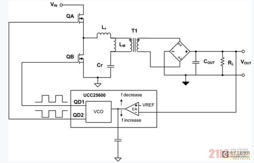
Figure 1 LLC resonant half bridge / controller
We can standardize and simplify the use of the first harmonic approximation transfer function M(f). In Equation 4 of M(f), the normalized frequency (fn) is defined as the switching frequency divided by the resonant frequency (fO). Although it is only an approximation method, the simplified equation is very useful in understanding how M(f) varies with input voltage, load, and switching frequency.
Adjusting the dc current to adjust the LED brightness One way to achieve LED brightness adjustment in an LLC resonant LED driver is to adjust the dc current through the LED. There is a problem with this: after the DC current changes, the output impedance of the LLC also changes. If you don't think about it, this change will bring about a change in M(f), which makes the LED driver design more complicated.
Problems with load changes Designing a half-bridge converter is not an easy task. Designers choose the magnetizing inductance (LM) according to ZVS requirements. They also adjust a1, Cr and Lr to get the ideal M(f) and frequency operating range. However, M(f) will change with Q, and Q will change as the output load (RL) changes. See Figure 2 for details.
The M(f) variation of the resonant LLC half-bridge LED makes voltage loop compensation and transformer selection more difficult, complicated, and confusing because there are so many variations to consider during the design process.
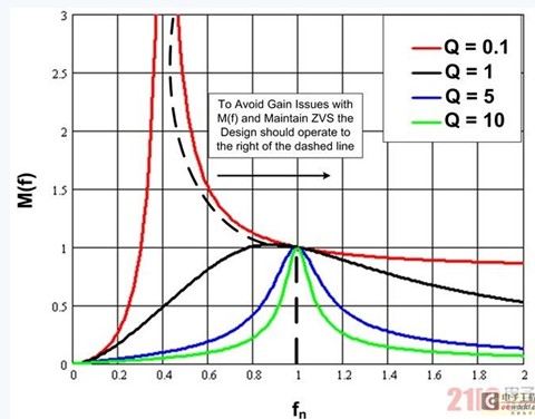
Figure 2M(f) varies with load.
The changing LLC gain curve (M(f)) causes a voltage controlled oscillator (VCO) control problem in the feedback loop. The VCO is typically controlled by a feedback error amplifier (EA (see Figure 1)). The switching frequency decreases as the EA output increases to increase the LLC gain and increase as the EA output drops. Ideally, in an LLC half-bridge design, the M(f) gain needs to start at a minimum at its maximum switching frequency, while M(f) rises as the frequency decreases.
The ideal M(f) range for normal operation is the right part of the dashed line (see Figure 2). We call this area the inductive area, when the LLC works under ZVS. The left side of the dashed line is the capacitor area where there is no ZVS on the main stage switching node. During large signal transients, the EA drives the VCO, requiring a lower switching frequency to increase the gain. As a result, the M(f) gain operates in the left area of ​​the dashed line and may not reach the ideal gain and cannot meet the control loop requirements.
At this point, ZVS is lost and the feedback loop will keep the LLC controller locked in that area. Now, the feedback error amplifier attempts to require a lower switching frequency to increase the gain that the power stage cannot achieve because the converter may operate in the right-hand region of the dashed line in Figure 2. When ZVS is lost, FETQA and QB consume more power and the FET is damaged by overheating. In order to avoid this problem in the design, all M(f) curves need to be analyzed, and then the minimum switching frequency (f) is appropriately limited to prevent the converter (M(f)) from working on the left side of the dotted line in Figure 2. area.
PWM Brightness Adjustment Simplifies the Design Process For LLC resonant half-bridge LED drivers that require brightness adjustment, one way to simplify the design process is to use a technique called PWM brightness adjustment. Figure 3 shows the functional schematic of an LLC converter, which is used by its LLC controller. In our case, we used UCC25710.
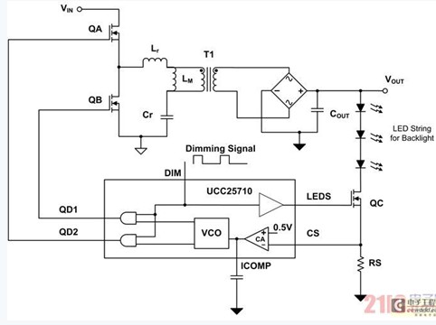
Figure 3. LLC half-bridge LED driver using PWM dimming technology.
This technique utilizes a fixed low frequency signal (DIM) that controls the FETQC, which is logically added to the QA and QBFET drivers. When the DIM signal is high, the LED backlight string is controlled to a fixed peak current (VRS/RS). Once DIM goes low, QA, QB, and QC turn off immediately. After QA, QB, and QC are turned off, the LED diode stops conducting and the output capacitor (COUT) stores energy to prepare for the next DIM cycle on time. See the waveform shown in Figure 4 for more details.
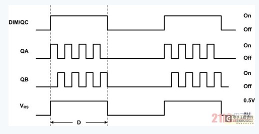
Figure 4 PWM brightness adjustment waveform
The adjustment of the average diode current (ID) is achieved by adjusting the duty cycle (D) of the DIM signal to control the brightness of the LED.
Although the LLC resonant half-bridge supplies power to the LED from the primary to the secondary, the load (RL) to LLC transfer function (M(f)) remains constant even though the average current of the LED varies with duty cycle.
When a fixed RL is used and Lr, Cr and LM are given, the equivalent reflection resistance (RE) is constant and Q remains unchanged. At this time, only one M(f) curve is obtained, which varies with frequency (see Fig. 5), and is not affected by the multiple curves obtained by the conventional LED brightness adjustment method using the variable RL (see Fig. 2). Only one M(f) curve is processed in the design, making loop compensation and transformer selection easier, simplifying the design process. In addition, you need to pay attention to another curve when setting the minimum switching frequency to ensure that ZVS is maintained. At this time, the minimum f is set to the peak of the single M(f) curve (see Figure 5).
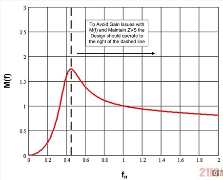
Figure 5 uses PWM brightness adjustment technology to drive the M(f) of the LED
It is not easy to design an LLC resonant half-bridge converter for LED driving. The dc/dc gain of a conventional LLC will vary over a wide range as the load changes. We need to evaluate a number of gain curves. This makes loop compensation and transformer design/selection more complicated and confusing. To simplify the design process, combining LLC and PWM dimming techniques is an ideal choice. This is because the LLC will withstand a fixed load (RL) during energization, but the LED current will change during brightness adjustment. As a result, the LLC gain variation is smaller, making loop compensation and transformer selection/design easier.
Reverse Conducting Thyristor(RCT) is also called Reverse- appreciation Thyristor.The characteristic is that a diode is connected in reverse parallel between the anode and cathode of thyristor, so that the transmitting junction of anode and cathode is short-circuited.As a result of this special circuit structure, it has high voltage resistance, high temperature resistance, short turn-off time, low switching voltage and other good performance.For example, the turn-off time of the reverse thyristor is only a few microseconds, and the working frequency is dozens of KHZ, which is better than the fast thyristor (FSCR).This device is suitable for switching power supply and UPS uninterrupted power supply. One RCT can replace one thyristor and one continuous current diode respectively.
Reverse Conducting Thyristor(RCT)
Reverse Conducting Thyristor,Original Reverse Conducting Thyristor,New Reverse Conducting Thyristor,Reverse-Conducting Thyristor 2200V
YANGZHOU POSITIONING TECH CO., LTD. , https://www.yzpst.com