Modern warfare requires more and more radar maneuverability. Especially for mobile land carriers such as vehicle radar antennas and launchers, after reaching the predetermined position, it is required to quickly set up an accurate horizontal reference. The manual manual leveling of the vehicle platform has been difficult to meet the requirements of the military for rapid erection, rapid withdrawal, and high-precision leveling of the platform. Compared with manual leveling, electromechanical automatic leveling has the characteristics of short leveling time, high leveling precision and high reliability. The design is based on single-chip microcomputer and CPLD as the control core, servo controller and servo motor are the electromechanical four-point support automatic leveling follow-up control system of the execution unit, which can realize the fully automatic and full-closed control of the automatic leveling of the electromechanical vehicle platform. . The advantages are short leveling time (less than 3 minutes), high leveling accuracy (less than 3'), high reliability, and work in harsh environments.
This article refers to the address: http://
System composition
Leveling principle
The leveling method usually has a 3-point or 4-point style, and a special multi-point type such as a 6-leg or more leg platform. The system adopts a 4-point leveling method according to the actual application. The four-point supported working platform X-axis and Y-axis are based on the installation position of the horizontal sensor to determine the two axial directions perpendicular to each other on the working platform surface. The leveling principle is shown in Figure 1.
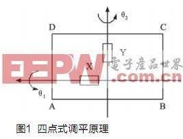
After the support legs of the work platform landed, the control system began to level. The highest point of the working platform can be found by the detection signal of the level sensor. The level sensor is placed on the work platform in the direction shown in Figure 1. The sensor output contains X and Y axis signals, which are digital signals that are linear with the horizontal error (angle). When X>0, Y<0, the leg A is the highest point; when X<0, Y<0, the leg B is the highest point; when X<0, Y>0, the leg C is the highest point; X When >0, Y >0, the leg D is the highest point.
Assume that the leg A is the highest point after the leg is grounded (the other legs are similar to the highest point), and the X-axis and Y-axis directions can be adjusted according to the signal of the level sensor. If the X-axis adjustment is performed first, the process is as follows: the legs A and D are not moving, and the legs B and C are simultaneously raised by a certain displacement, that is, the working platform rotates around the legs A and D, and the legs B and C rise simultaneously. The rising value is determined by the control system based on the X-axis feedback value of the level sensor until the X-axis is horizontal. The Y-axis adjustment is similar to the X-axis. If the X and Y axes of the table are adjusted to a horizontal state, the table is considered to be in a horizontal state. The horizontal error of the 4-point leveling is q2=q12+q22, and q1 and q2 are the angular accuracy of the horizontal sensor, respectively. If the control accuracy of both sensors is δ, then the horizontal error.
One of the main problems facing the 4-point and multi-point leveling design is the virtual leg phenomenon, that is, one leg is stressed or suspended, which is not allowed during the leveling process. When the load on the platform is uniform, the force of the four support points should be uniform. The treatment method of the system design is to carry out the rough leveling (setting a rough precision) after supporting the platform, so as to make the force of the four support points relatively close. Then, level the level according to the leveling accuracy set by the system. In this way, the process of adjustment does not appear that the force of one leg is too small (virtual leg), thereby effectively preventing the occurrence of the virtual leg phenomenon.
Hardware composition
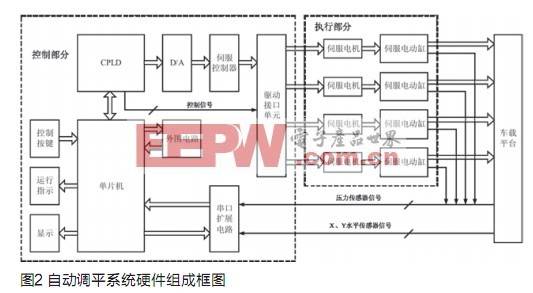
The hardware composition of the automatic leveling system is shown in Figure 2. The system is mainly composed of a control part, a level sensor, a pressure sensor, a servo controller, a servo motor and a servo electric cylinder.
The horizontal sensor (X and Y directions) measures the inclination of the vehicle platform, and transmits the inclination data of the X direction and the Y direction to the control part through the RS232 serial port, and the baud rate is 9600 bit/s. The horizontal sensor used in this system has a measurement accuracy (zero position) of 0±20" and a resolution of ≤4", which fully meets the requirements of platform inclination measurement and leveling.
The pressure sensor is used to measure the pressure of the four support legs. The measurement range is 0-9000kg. The pressure data is sent to the control part through the RS232 serial port. The baud rate is 9600bit/s.
The control part is mainly composed of a control board, a servo drive and a drive interface unit. The control board is the core of the control part, and is mainly composed of a single chip microcomputer, a CPLD, a multi-channel DAC, a multi-serial port expansion circuit, an RS232 level conversion circuit, and a watchdog circuit. When the operator sends a control command to the control board through the button, the CPU reads the data sent by the level sensor and the pressure sensor to determine and form a control strategy, generates a control signal sent by the DAC to the servo controller, and then controls the drive interface circuit to drive the certain One servo motor runs until it is leveled. For operational safety, the entire leveling operation is indicated by sound and light. The control part displays the inclination angle and pressure data in real time, which is convenient for the operator to monitor.
The leveling process of the vehicle radar platform is completed in two stages. The first stage is the erection phase, that is, after the vehicle radar reaches the position, the four supporting legs are first controlled to land and the floor is detected. After the system is powered on, the operator only needs to press the “erase†button on the operation panel to control the system to drive the servo motor to lift the support leg, and at the same time, to detect whether each support leg is on the ground, and stop the lifting of the leg when a supporting leg touches the ground. When all four support legs are on the ground, the landing test ends. The second phase is the leveling phase. The operator presses the “leveling†button on the operation panel, and the single-chip computer reads the inclination data of the current vehicle platform and the force data of each support leg sent by the pressure sensor, according to the inclination data and the pressure data, according to the control. The strategy drives the corresponding motor to raise the corresponding support leg until the inclination of the seat reaches the requirements of the radar system.
System program workflow
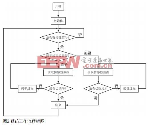
The workflow diagram of this system is shown in Figure 3.
Conclusion
The radar automatic leveling system is an important part of the vehicle radar. It plays a decisive role in improving the measurement performance of the radar, such as the measurement accuracy of the target angle and the speed of the entire rack setting and withdrawal. The system adopts single-chip microcomputer and CPLD control, and applies AC servo control, which greatly improves the horizontal precision and adjustment time of the platform when the radar antenna is erected, and has the characteristics of high reliability and good maintainability.
Personal Tracker,Watch GPS Tracker,Personal Watch Tracker
OBD2 Vehicle GPS Tracker,GPS Vehicle Tracker,GPS Motorcycle Tracker Co., Ltd. , http://www.cn-gpstracker.com