Electronic circuit diagrams play a crucial role in understanding and designing electrical systems. There are several types of circuit diagrams, each serving a specific purpose. Here's an overview of the main categories:
1. **Schematic Diagram**
A schematic diagram is a visual representation that shows the working principle of an electronic circuit. It uses standardized symbols to depict components and their connections. This type of diagram is essential for both design and analysis because it clearly illustrates how the circuit functions. By identifying the symbols and their relationships, you can understand how the circuit operates. The image below shows a schematic of a radio circuit.
 2. **Block Diagram**
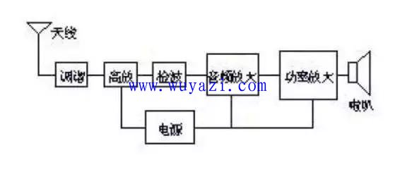
A block diagram is a simplified version of a schematic, where each section of the circuit is represented as a block. These blocks show the general function of different parts of the system, with lines or arrows indicating the flow of signals or data between them. While it doesn't provide detailed component information, it gives an overall view of the circuit’s structure. The following image shows the block diagram of the same radio circuit.
2. **Block Diagram**
A block diagram is a simplified version of a schematic, where each section of the circuit is represented as a block. These blocks show the general function of different parts of the system, with lines or arrows indicating the flow of signals or data between them. While it doesn't provide detailed component information, it gives an overall view of the circuit’s structure. The following image shows the block diagram of the same radio circuit.
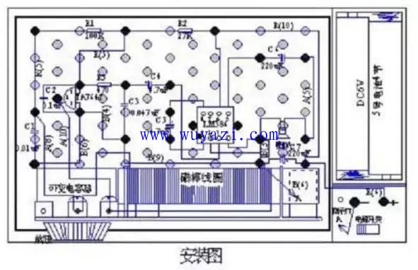
 3. **Assembly Drawing**
Assembly drawings are used to guide the physical construction of a circuit. They often show the layout of components on a board or a prototype. These diagrams are especially useful for beginners, as they make it easier to assemble the circuit step by step. In many cases, printed circuit boards (PCBs) are used, which are then referred to as "plate layouts." Here's an example of an assembly drawing using a screwboard as a base.
3. **Assembly Drawing**
Assembly drawings are used to guide the physical construction of a circuit. They often show the layout of components on a board or a prototype. These diagrams are especially useful for beginners, as they make it easier to assemble the circuit step by step. In many cases, printed circuit boards (PCBs) are used, which are then referred to as "plate layouts." Here's an example of an assembly drawing using a screwboard as a base.
 4. **Printed Circuit Board (PCB) Layout**
A PCB layout is a detailed drawing that shows the physical placement of components and the conductive paths connecting them. It is created after the schematic and block diagrams are finalized. The PCB is made by etching copper layers on an insulating substrate, allowing components to be mounted and connected. PCBs are widely used in modern electronics due to their efficiency and reliability. They come in various forms, including single-layer, double-layer, and multi-layer boards, and are used in everything from consumer electronics to aerospace applications.
Understanding these different types of circuit diagrams is essential for anyone involved in electronics. While the schematic is the most important, mastering the others helps in building, analyzing, and troubleshooting circuits effectively. Whether you're a student or a professional, learning to interpret these diagrams is a valuable skill in the field of electronics.
4. **Printed Circuit Board (PCB) Layout**
A PCB layout is a detailed drawing that shows the physical placement of components and the conductive paths connecting them. It is created after the schematic and block diagrams are finalized. The PCB is made by etching copper layers on an insulating substrate, allowing components to be mounted and connected. PCBs are widely used in modern electronics due to their efficiency and reliability. They come in various forms, including single-layer, double-layer, and multi-layer boards, and are used in everything from consumer electronics to aerospace applications.
Understanding these different types of circuit diagrams is essential for anyone involved in electronics. While the schematic is the most important, mastering the others helps in building, analyzing, and troubleshooting circuits effectively. Whether you're a student or a professional, learning to interpret these diagrams is a valuable skill in the field of electronics.
72V Battery Pack ,Lithium Ion Battery Pack,Lithium Battery Pack,Battery Power Pack
Zhejiang Casnovo Materials Co., Ltd. , https://www.casnovonewenergy.com