VIPer53 is a new generation of highly integrated off-line switch IC, which uses ST's patented vertical smart power technology (VlPower), which is highly integrated and has a built-in power MOSFET with multiple drain mesh process (MD-Mesh). Target applications include set-top boxes, DVD players, power converters for video recorders, and auxiliary power supplies in televisions, PCs, and travel adapters. The VIPer53 uses a system-on-a-chip that contains the system's control section and power MOSFETs in the same package. This new packaging process meets the application needs of all monolithic integrated circuits, especially for power converters where power requirements are increasing and dedicated thermal design cost control is more stringent. In this paper, a 30W set-top box dedicated switching power supply is set up with VIPer53, and the design method and experimental results are given.
1 How does VIPer53 work?
The VIPer53 integrates an enhanced current mode PWM controller with a high voltage MD.Mesh power MOSFET. The internal structure of VIPer53 is shown in Figure 1. It includes all the modules required on the primary side of the switching circuit. The control part includes the high-voltage current source for starting the converter, the pulse width modulation driver and various protection functions, such as overvoltage protection and thermal shutdown. With cycle-by-cycle current limit and load protection, the minimum breakdown voltage of the power MOSFET is 620 V, and the on-resistance RDSFET is 1 Ω at 25%. Pin VDD
The switching frequency can be set externally by connecting a resistor-capacitor network of the OSC pin up to 300 kHz. When the switching power supply is powered up, an internal high-voltage current source between the drain pin and pin VDD supplies power to the device and charges a VDD external capacitor. When the VDD voltage reaches the voltage threshold VDDon, the internal high-voltage current source is turned off, the device begins normal operation, and the high-frequency transformer auxiliary winding continues to supply power to the VIPer53 device.
The feedback control system of VIPer53 belongs to the current control, and the system function is realized by the foot COMP. The control refers to comparing the current flowing through the power MOSFET and the flyback transformer with a feedback signal generated by the output voltage of the regulating circuit, and the result of the comparison determines the on-time of the MOSFET.
The first advantage of VIPer53 is to reduce energy consumption to near zero under no-load conditions, enabling power supply manufacturers to meet new and more stringent ecological standards, such as the Energy Star Program. Second, because of the on-state resistance RDS(on) Low, power conversion efficiency is significantly improved, and the use of a heat sink is eliminated, thereby avoiding an increase in manufacturing cost. Typically, the DIP-8 package can output 30W, and the Power-SO-10 package can output 40W. The voltage range is ACR5~265V.
An important function of VlPer53 is the overload delay done by the foot TOVL. If the pin COMP voltage exceeds 4.35V, the overload protection will start and the external capacitor connected to the TOVL pin will begin to charge and the MOSFET will continue to switch. During this time, the drain current is limited to 1.6A. If the overload condition remains unchanged, the MOSFET is turned off when the TOVL capacitor voltage reaches the threshold voltage VOVLth. At this point, the VDD voltage drops. When the VDDoff threshold voltage is reached and the internal high voltage current source is turned on, a new start cycle begins. If the overload or short circuit condition persists, VIPer53 will enter an endless restart sequence. The charging time of the external capacitor of the pin TFOVL is the delay time. The time tOVL must be greater than the starting time tss of the switching power supply because the auxiliary winding cannot provide sufficient power to the system during this time. 2 set-top box power requirements
In all functional modules of digital set-top boxes, there are specific supply voltage requirements from receivers, 32-bit microprocessors, digital circuits with different bias voltages, peripheral devices, and input/output circuits. Digital set-top boxes use digital signal processors (DSIs) and microprocessors (MPUs) and support embedded operating systems to meet the high-speed computing and low-power requirements of today's embedded audio, video and communications applications. In order to fully utilize the dynamic power management capability, some processors integrate an on-chip switching regulator, which can generate 0.7~1.2 V configurable core operating voltage by using 2.25~3.6V external power supply voltage. This saves external power components. In the set-top box power supply, in addition to the +3 3V and +5V output for the digital signal processor, microprocessor and other control chipset power supply, also need +12V, +24V and +30V output, for example, in the new generation of set-top boxes, many For example, hard disk, DVD, etc., all need +12V power supply. For the set-top box power supply, due to the high output power, the number of output channels is large, and because of the low efficiency of the linear regulated power supply, the narrow voltage range of the grid, the poor performance of the voltage regulator, and the bulkiness, it tends to adopt a mature switching power supply.
3 30W set-top box switching power supply high-frequency transformer design
The technical specifications of a five-output set-top box power supply are as follows:
1) Output 3.3V/2A;
2) Output 5.V/l A:
3) Output 12V/100mA;
4) Output 24V/500mA;
5) output 30V/50 rnA;
6) The total power output is close to 30W.
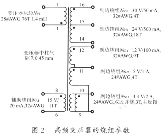
Technical requirements: The core is EE28 vertical and the core material is PC40. The transformer is subjected to oil immersion treatment, and the insulation withstand voltage between the windings is not lower than AC 2500V, lmin; the insulation voltage between the layers is not lower than AC 1500V, l min. The insulation voltage of all coils and the case is not lower than AC 2500V, lmin.
4 Circuit design of set-top box switching power supply
The VIPer53 and peripheral devices as well as the input and output side circuits and parameters of the entire transformer are shown in Figure 3. The auxiliary winding provides a stable 15V voltage directly to VIPer53 via diode D1D. The overload delay circuit consists of the foot TOVL outside R2D" and C3D. The device parameters ensure that the delay time is greater than the startup time of the switching power supply. The enhanced current mode control peripheral circuit consists of R3D, C4D and C5D, which can set the dynamics of the switching power supply. characteristic.
The input EMI filter uses a common-mode coil, common-mode and differential-mode capacitors to filter the differential mode and common-mode interference. See Figure 3 for the power supply and input. An NTC resistor is added to the power input to limit the magnitude of the inrush current when the system is powered up. The high-frequency transformer is based on a standard RCD clamp circuit, and the TRANSL circuit can also be used to reduce standby loss. Capacitors ClE and C2F are used to reduce the common mode interference generated by high frequency transformers. The switching frequency is 100 kHz and is set by resistors RlD and ClD-n. The built-in burst mode circuit can skip some switching cycles and reduce the equivalent switching frequency during standby and light load. According to the voltage of the foot COMP, VIPer53 provides a two-value blanking time, that is, the blanking time is 150 ns and 400 ns at a voltage of 0.5 V and lV.
In this design, the maximum output of load power and output current is +3 3V, +5V and +24V output. Since 24V is the selected output, the output power of +3.3V and +5V is close, so the main voltage feedback adopts +3 3V and 5V. Output. The feedback voltage is supplied by an adjustable precision shunt regulator TL431 and an optocoupler. The voltage of the optocoupler collector determines the peak drain current of the BIPer53. The feedback comparator is connected across the cathode and reference pins of the TL431. C6D and R5D are the frequency compensation networks of TL43l. R7D, R8D and R9D are proportional feedback resistors, so that the +3.3V and +5V outputs are fed back according to a certain ratio, so that the load regulation rate of both output voltages can reach ±5%. The rest of the output is determined according to the turns ratio of the high frequency transformer. In view of the large output power of +3 3V, +5V and +24v, the post-stage Lc filter is added to reduce the ripple voltage. 5 Experimental results and analysis
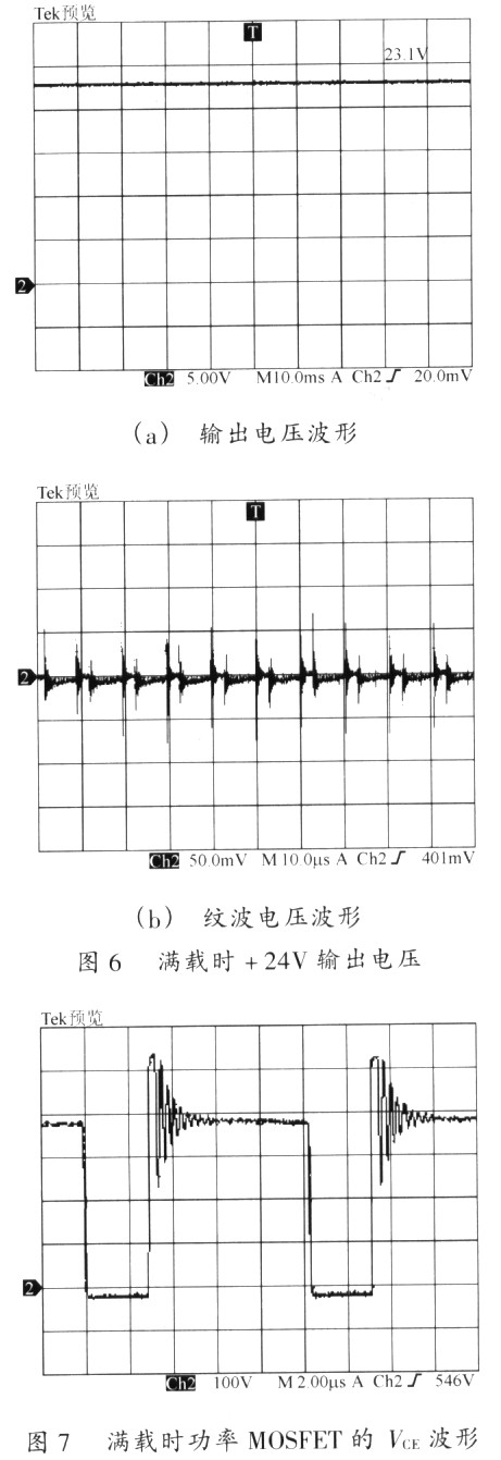
The production and experiment of the set-top box switching power supply was completed in the laboratory, and the board size was 74mm×186mm. The maximum duty cycle of the measured minimum input AC voltage of 85V is 45%, and the maximum duty ratio of the rated input AC voltage of 220V is 28%. The quasi-peak and average curves of continuous conduction disturbance at the input of the power supply are in accordance with EN55022CLASSB. When AC 220V power supply, the working power supply provided by the auxiliary winding at light load and full load is 15V, and the maximum working current is 20mA. The average output of +3.3V, +5V, +12V, +24V, and +30V at light load is 3.48V, 5.52V, 14.0V, 25.0V, and 30.8V, respectively, and the maximum ripple voltage peak-to-peak value is less than 20mV. Outputs 3.20V, 5.20V, 12.1V, 23.1V, and 30 at full load. OV, the maximum ripple voltage peak-to-peak is 175mV, 150mV, 250mV, 80mV and 80mV. The output voltage waveforms of the +3.3V, +5V and +24V outputs at full load and the corresponding ripple voltage waveforms are shown in Figure 4, Figure 5 and Figure 6, respectively. The voltage VCE between the collector D and the emitter S of the power MOSFET is shown in Fig. 7. It can be seen that the duty ratio is 28%, less than 50%, the VCE peak is 540V, and the VCE peak at no load is 450V, which is smaller than the MOSFET. The breakdown voltage is 620V.
6 Conclusion
Based on the analysis of the requirements of the set-top box for switching power supply, this paper uses the power integrated circuit VIPer53 to give a power supply with 5 outputs, suitable for universal AC input, and good conduction EMI performance. Experiments show that the set-top box power supply using VIPer53 has the advantages of convenient design, high efficiency, small size, light weight, etc., and low standby loss, no need for additional heat sink, and is an ideal power IC for switching power supply.
references:
[1]. VIPer53 datasheet http://
[2]. Power datasheet http://
[3]. DlD datasheet http://
[4]. 400ns datasheet http://
[5]. TL431 datasheet http://
:
A buyer may need to find a durable and reliable metal smartphone case to protect his or her iPhone investment.
The case does not add bulk to the thin smartphone appearance and prevents scratches from damaging the device. Its packaging includes an extra lower frame for personalization.
it has a solid build and smooth lines. After the product fell several times, it did not receive any damage.If you are looking for high tech style combined with ultimate protection then you`ve found your case. Our protective, aluminum iPhone cases are CNC machined from aircraft grade aluminum and have withstood some pretty intense impact and drop testing. Not to mention the award-winning design that has everyone talking.
Metal Cnc Machined Phone Case,Cnc Machined Metal Mobile Phone Case ,Cnc Machined Phone Case,Cnc Machined Mobile Phone Shell
ShenZhen Elite Technology Co.,Limited , http://www.eli-tec.com