Application of Rotary Encoder in Online Speed ​​Detection Control
introduction
This article refers to the address: http://
The project is a technical transformation project for a cable factory. The equipment to be transformed is a coiled cable-forming machine manufactured by the principle of beam-line. The modification is to replace all electrical control systems. The cable reel of the cable machine is fixed, and the take-up reel is fixed on the disc gallows while performing the double movement of the twisting and winding. During operation, the cable take-up movement is completed under the driving of the DC motor of the cable tray, and the cable is arranged neatly on the take-up reel under the driving of the cable motor. Under the driving of the large-disc motor, the axial rotation of the disc gallows is driven by the gear box to complete the cable stranding movement, which is the key to ensure the pitch. The linear speed is determined by the rotational speed of the take-up reel. If the rotational speed of the take-up motor is constant, the take-up reel will become thicker as the take-up reel becomes thicker. Therefore, to ensure a constant take-up speed, it is gradually reduced. The speed of the take-up motor.
1 system design principle
According to the production process requirements of the cable, the cable speed of different types of cables is constant. Usually, the running speed of the cable is detected by the cable driving rotary encoder. The cable speed measurement speed diagram is shown in Figure 1.
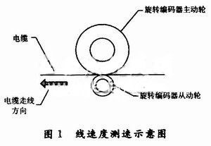
In this project, the rotary encoder model is the TRDJ1000 series, which outputs 1 000 pulses per revolution. Therefore, based on the number of pulses detected within a certain period of time, the cable routing speed can be calculated. In practical applications, it is mounted coaxially with a rotating encoder with a very high machining accuracy and a circumference of 500 mm. The drive wheel is in contact with the rotary encoder, and the drive wheel is in contact with the cable. During the cable production movement, the measuring wheel is rotated by friction, so that the linear displacement (length) of the cable is converted into the pulse digital signal output of the rotary encoder.
For each revolution of the rotary encoder, the number of counting pulses is NP (number of pulses / revolution), then the angular resolution of the rotary encoder (unit: (°) / piece) is:
P=360/NP
Assuming that the active guide wheel radius fixed on the rotary encoder shaft is rm, the rotary encoder displacement resolution (unit: m/piece) is:
Ps=27Ï€r/NP
At this time, if the number of counting pulses is N (number), the displacement amount S (unit: m) measured by the rotary encoder is:
S=Ps·N
The cable routing speed V (unit: m/s) is:
V=S/T
Where: T is the time (unit: s) used to receive N pulses.
2 hardware circuit design principle
T-INDENT: 0px; PADDING-TOP: 0px; WHITE-SPACE: normal; LETTER-SPACING: normal; BACKGROUND-COLOR: rgb(255,255,255); orphans: 2; widows: 2; -webkit-text-size-adjust: Auto; -webkit-text-stroke-width: 0px"> The detection circuit uses the AT89C51 microcontroller as the control core. As shown in Figure 2, the pulse output from the rotary encoder is level-converted to become a TTL of 0 to 5 V. The level pulse is sent to the external interrupt INT0 terminal of AT89 C51 MCU. Each time a pulse is received, the MCU interrupts once, and the counting pulse memory is incremented by 1. After comparing with the standard pulse value, the P0 port of the MCU outputs a given digital value. After D/A conversion, it becomes a given value analog quantity, and is sent to the take-up motor speed controller to control the motor speed. The D/A conversion chip here uses 8-bit data input and four-channel analog output TLC7226IDW. To improve the motor speed control accuracy, other 10-bit, 12-bit data input D/A converter chips can be selected.
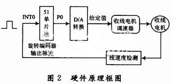
During operation, when the take-up motor drives the cable to move, the driving wheel of the rotary encoder is rotated, so that the rotary encoder rotates and outputs a pulse. The pulse is sent to the optocoupler for isolation, shaping, level conversion, and is sent to the 12 pin of the AT89C51. The external interrupt INTO performs pulse counting. Each time a pulse is received, the microcontroller executes the external interrupt INT0 subroutine once, and the pulse count memory is incremented by one. For example, it is read once every 1 s, so that it can be compared with the standard number of pulses according to the number of counting pulses, and therefore, the current linear velocity can be judged.
The line speed is calculated as follows:
For example, the linear velocity V is required to be 0.1 m/s.
Rotary encoder output pulse number per second = V · Np / C
Where: C is the circumference of the drive wheel of the rotary encoder (unit: m). Therefore, when the linear velocity is 0.1 m/s, the rotary encoder outputs a standard number of pulses per second = 0.1 × 1000 / 0.5 = 200 / s.
3 software design
Runs in a timer interrupt, executed once per second in the timing subroutine. That is, the number of pulses received per second is the same as the standard pulse. The line speed control subroutine is shown in Figure 3.
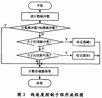
First, the value of the read pulse count memory is compared with the standard pulse number, equal to the standard pulse, and the pulse count memory value is cleared, indicating that the trace speed is equal to the standard speed; if it is greater than the standard pulse number, the line speed is greater than the standard line speed. Therefore, the governor set value must be reduced by 1, so that the take-up motor speed is reduced; if it is less than the standard pulse number, the line speed is less than the standard line speed, the governor set value must be increased by 1, so that the take-up motor speed Increased to form a closed loop linear speed control feedback system that controls the take-up motor rotation speed so that the line speed remains constant.
4 Conclusion
The above line speed control system has been successfully applied in the actual technical transformation, saving nearly 10 million yuan of technical transformation funds for the enterprise. The results show that the system has the characteristics of stable and reliable operation, simple circuit, high measurement accuracy and low cost. It fully meets the requirements of cable production process. Its simple circuit design and typical control method have high reference value.
R&M Vape,R&M Squid Box,Randm Game Box,Randm Disposable Vape
Shenzhen Zpal Technology Co.,Ltd , https://www.zpalvapes.com