Design of a new type of smart car motor drive circuit
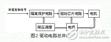
In the electromechanical control system, most of the control signals are output by the microcontroller, such as a microcontroller, CPLD, DSP, and so on. These microcontrollers must ensure the stability of the work and ensure low power consumption. Therefore, the operating voltage of these control chips is relatively low, and the common ones are 5V, 3.3V, 1.8V, etc. These voltages can only represent the control signals. Does not have the ability to drive large power loads. Since the purpose of this circuit is to drive the 540 motor on the smart car, the motor has the characteristics of high torque and large current. Therefore, a drive circuit must be added between the control signal and the 540 motor to improve the driving capability, so that the single chip can be used for the motor. Take control. In this paper, the BTS7960 high-current low-voltage motor driver chip is selected for circuit design. The overall block diagram of the designed driver circuit is shown in Figure 2.
The BTS7960 is a high current integrated chip for motor drive. It consists of a P-channel high-side MOSFET and an N-channel low-side MOSFET combined with an integrated driver IC to form the half of the H-bridge that can withstand high currents. Since the P-channel high-side switch eliminates the charge pump, electromagnetic interference (EMI) is reduced. The driver IC integrated in the BTS7960 makes interface with the microcontroller very easy, and has logic level input, current detection diagnostics, slope correction, dead time generation and over temperature, over voltage, under voltage, over current and Short circuit protection function. Two BTS7960s can be connected to form an H full bridge. The BTS7960 on-state resistor has a typical value of 16mΩ and a drive current of up to 43A.
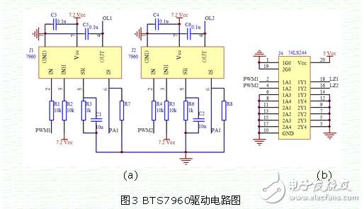
In the race of smart cars, the track is varied, with straight, curved curvature and continuous S-bend, so the motor works in a state where the speed is continuously changing. The acceleration deceleration of the motor can be achieved by adjusting the duty cycle of the PWM wave in one direction. However, in more complicated cases, the motor needs reverse braking of voltage reversal to achieve deceleration. For example, the high-speed driving state until suddenly enters a curve with a large curvature. At this time, it is not enough to stop the unidirectional PWM wave output, and the output of the reverse PWM wave is required. Therefore, the circuit design requires two BTS7960s. H full bridge to achieve the positive and negative rotation of the motor. The circuit diagram of the design is shown in the figure.
KNM2 Series Moulded Case Circuit Breaker
KNM2 series Moulded Case Circuit Breaker is MCCB , How to select good Molded Case Circuit Breaker suppliers? Korlen electric is your first choice. All moulded Case Circuit Breakers pass the CE.CB.SEMKO.SIRIM etc. Certificates.
Moulded Case Circuit Breaker /MCCB can be used to distribute electric power and protect power equipment against overload and short-current, and can change the circuit and start motor infrequently. The application of Moulded Case Circuit Breaker /MCCB is industrial.
Korlen electric also provide Miniature Circuit Breaker /MCB. Residual Current Circuit Breaker /RCCB. RCBO. Led light and so on .
KNM2 series Molded Case Circuit Breaker,KNM2 series Small Size Molded Case Circuit Breaker,KNM2 series Electrical Molded Case Circuit Breaker,KNM2 series Automatic Molded Case Circuit Breaker
Wenzhou Korlen Electric Appliances Co., Ltd. , https://www.zjthermalrelay.com