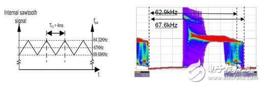
We know that in fixed-frequency PWM controllers, narrow-band emissions usually occur at the switching frequency, and the energy of their continuous harmonics is getting lower and lower. The focus of Frequency Jitter is to disperse the harmonic interference energy. We make the operating frequency of the switching power supply not fixed, but periodically change, because the EMI emission is distributed over a wide frequency range instead of Operating at narrowband frequencies reduces peak EMI emissions. The jitter oscillator will also reduce the peak value of the harmonic frequency (ie, the frequency that is a multiple of the switching frequency). The reduction in the amount of transmission depends on the choice of modulation frequency (jitter rate), the jitter bandwidth, and the resolution bandwidth of the receiver.

Note: Of course, the effect on reducing high frequency non-harmonic emissions is minimal. These emissions are caused by the ringing of the switching node due to parasitic LC circuitry, diode reverse recovery current, and the like. Adding a buffer, a gate drive resistor, or using a soft recovery diode is a common solution to reduce these emissions.
Disadvantage: The jitter oscillator will add a small amount of ripple to the output voltage (the frequency of the ripple is equal to the jitter frequency), which is usually much smaller than the frequency (switching frequency) of the output voltage ripple due to the capacitance ESR and the inductor current. The amplitude of the wave is relatively low compared to the amplitude of the nominal output ripple.
In-chip implementation form:
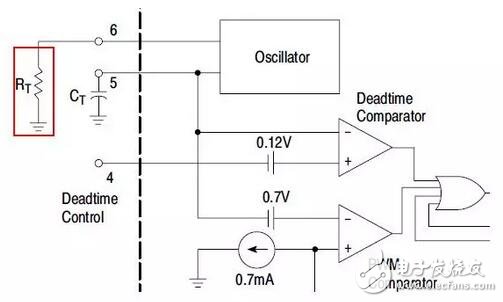
Current PWM controllers typically use an external resistor to set the operating frequency. Normally, the operating frequency rises as the resistance value decreases, and the oscillator programming pin (RT) inside the controller is regulated to a constant voltage. A programming resistor connected to the programming pin sets the current source output from the programming pin. The proportional current is also fed to the internal timing capacitor, and the period of the ramp voltage on the timing capacitor determines the oscillator frequency.
External resistors to set the operating frequency principle: Normally, the operating frequency rises as the resistance value decreases.
The internal oscillator programming pin (RT) of the controller is regulated to a constant voltage, and the programming resistor connected to the programming pin sets the current source output from the programming pin. The proportional current is also fed to the internal timing capacitor, and the period of the ramp voltage on the timing capacitor determines the oscillator frequency.
Two external circuits:
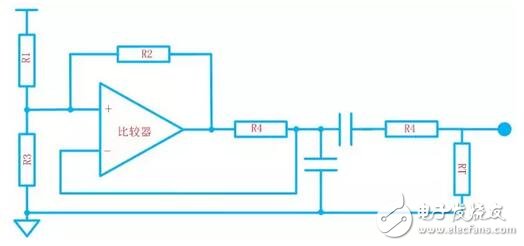
Comparator circuit
Op amp circuit
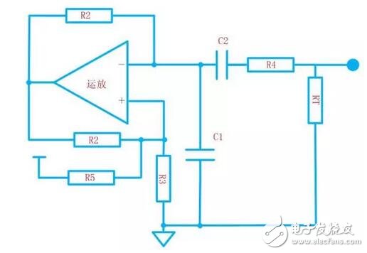
The operation of the two circuits is the same. After power-on, the output of the comparator/op amp is high. The two figures charge the capacitors through R2 and R4 respectively. When the voltage is above the high threshold, the op amp/comparator flips, the input threshold switches to a low level, and then the capacitor discharges.
The voltage on the pull-down capacitor is similar to a triangular wave.
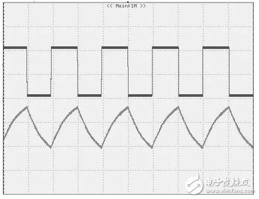
The triangular wave modulation can control the current of the RT pin to realize the jitter of the PWM oscillator. A series resistor is used to set the modulation jitter percentage. The low frequency triangular wave is changed at the resistor voltage by a coupling capacitor.
China leading manufacturers and suppliers of Level 2 Charger,Ev Charging Stations, and we are specialize in Charging Station,Flexible Group Charging Station, etc.
Level 2 Charger,Ev Charging Stations,Charging Station,Flexible Group Charging Station
Shenzhen Hongjiali New Energy Co., Ltd. , https://www.hjlcharger.com