LED lighting has become the focus of everyone's attention because of its high energy saving, long life and environmental protection. In recent years, the high-brightness LED light source has experienced rapid advancement in its manufacturing technology, and its production cost has been declining. Nowadays, the use of LED light source as a high-brightness, high-efficiency, energy-saving, carbon-free energy-saving lighting source has become a global mass. Demand, an emerging industry that manufactures LED lighting is on the rise, the industry chain is getting better and better, and technology is being updated every day.
BP2808 basic working principle
The BP2808 is a constant current control chip that specifically drives LED light sources. The BP2808 operates in a continuous current mode step-down system. The chip controls the peak current and ripple current of the LED source to achieve a constant average current of the LED source. The chip implements constant current control, analog dimming, and PWM dimming with very few external components. The system application voltage ranges from 12VDC to 600VDC, and the duty cycle can be up to 100%. It is suitable for AC 85V-265V wide voltage input, mainly used for non-isolated LED lamp power drive system. The BP2808 uses a patented source drive and constant current compensation technology to make the current driving the LED source constant, varying less than ±3% from AC 85V-265V. Combined with BP2808 patented drive system application circuit, the 18W LED fluorescent lamp practical solution has a system efficiency higher than 90% in the range of AC 85V-265V. In the AC 85V-265V input range, the BP2808 can drive LED light source arrays from 3W to 36W, so it is widely used in E14/E27/PAR30/PAR38/GU10 and other LED and LED fluorescent lamps.
The BP2808 features multiple LED protection features including LED open circuit protection, LED short circuit protection, and over temperature protection. Once a system failure occurs, the power system automatically enters the protection state until the fault is removed and the system automatically re-enters the normal operating mode. Multiplexed DIM pins allow for LED analog dimming, PWM dimming, and dynamic temperature protection of the fixture system. The BP2808 is available in an SOP8 package.
Typical design of LED fluorescent lamp application
There are many kinds of LED light source strips for LED fluorescent lamps. At present, non-isolated schemes are dominant because of their high efficiency, small size and low cost, while the majority of LED fluorescent controllers are used to drive LED fluorescent lamps. . In fact, traditional fluorescent fluorescent lamps are non-isolated solutions.
Taking the AC176V-264V full-voltage input as an example, BP2808 is used as the main chip to design a multi-string and multi-integrated LED fluorescent lamp with low power and multiple LED light sources. The block diagram of the whole system scheme is shown in Figure 1. The whole circuit is protected by surge/lightning protection, EMI filtering, full bridge rectification, passive power factor correction (PPFC), starting voltage (including feedforward compensation, feed power supply after power on, drive softening), constant current compensation, PWM control, source drive, LED light source array, and sampling resistor, Toff time setting, energy storage inductor, freewheeling diode and other components.
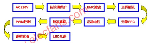
Figure 1: Block diagram of the 18W LED fluorescent system design.
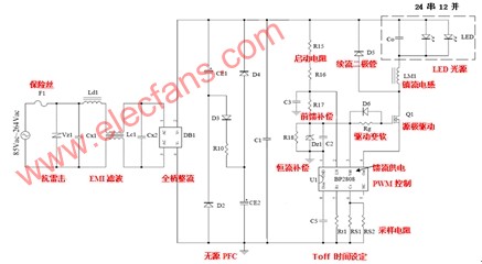
Figure 2: Practical circuit diagram of the 18W LED fluorescent lamp.
Seen from AC220V, the AC mains inlet is connected with 1A fuse F1 and anti-surge/lightning varistor Vz1; followed by EMI filter, composed of Ld1, Lc1 and Cx1, Cx2; DB1 is a full-bridge rectifier, the internal is 4 high-voltage silicon diodes; CE1, CE2, R10, D2~D4 form a passive power factor correction circuit; BP2808 chip is R15, R16 start-up resistor step-down through R17, C3 feedforward compensation, and by Dz1, C2, R18 and BP2808 The internal circuit is composed of a patented constant current compensation circuit to supply power to the BP2808 control circuit. After the system is started, the quiescent current of the control circuit itself is small, and the feed diode from OUT to VCC can provide working power to the BP2808. The current passing through resistor R15-17 will be greatly reduced, so the total system power consumption is also greatly reduced, and the system efficiency is significantly improved. The patented source driver circuit consists of MOS transistors Q1, D6, Rg, Rt, Rcs and BP2808 internal circuits. Its remarkable features are effective reduction of power consumption and improvement of constant current accuracy. The source-driven driving circuit reduces the system current consumption, especially reducing the current on the R15-17 in the conventional high-voltage differential power supply path, thereby reducing power consumption and improving efficiency. D6 and Rg can make the switch open drive soft, and the shutdown drive remains strong, which not only improves EMI, but also does not sacrifice efficiency. An output filter capacitor C0 in parallel with the LED source is used to reduce current ripple on the LED source.
The CS terminal of BP2808 collects the peak current on the current sampling resistors Rs1 to Rs2, and the internal logic controls the pulse duty of the OUT pin signal in a single cycle for constant current control. The output constant current is merged with the freewheeling circuit of D5 and LM1. The LED light source is supplied with constant current. When the LED light source array combination is changed, the resistance values ​​of the resistors Rs1 to Rs2 also change, so that the output current of the entire circuit satisfies the requirements of the LED light source array combination.
The arrangement of the PCB board is the key to making the product, so the wiring of the PCB board should be designed according to the requirements of power electronic safety regulations. This circuit can be used in T10 and T8 fluorescent tubes. Because the space of the two tubes is different, the width of the two PCBs will be different. The height of all parts should be reduced to fit the T10 and T8 tubes. Figure 3 is a photo of the T10 constant current source board with 30 components mounted on a 0.8 mm thick epoxy single-sided printed board.
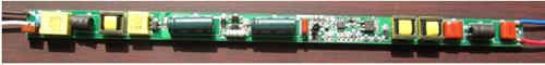
Figure 3: Physical photo of the 18W LED fluorescent switch constant current source
If you design AC85V--264V full voltage input, you must also consider PFC, LED light source array can be designed as 0.06W white LED 12 series, 24 series parallel scheme. When BP2808 is designed as LED fluorescent lamp power supply, it is recommended that the output voltage be <100VDC and current <600mA.
There are several LED fluorescent lamp driver ICs that can be used at present, and their performance parameters are different. Now list 1 is for design selection. It can be seen that the BP2808's fixed Toff mode of operation, 100% duty cycle, chip operating current of only 0.2mA, efficiency of 92%, constant current compensation and the use of unique source drive mode make it suitable for LED lighting. obvious advantage.
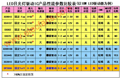
Table 1: Comparison table of performance parameters of LED fluorescent lamp driver IC products.
Key technologies of BP2808
Two patented application circuits, constant current compensation and source drive, make the BP2808 application more convenient and more feature-rich. As can be seen from Figure 4, the internal circuit of BP2808GND and LN and R3, C3, R4, Dz1, C2 form a patent application circuit for constant current compensation; the internal circuit of BP2808Vcc, CS and OUT and the source of Q1, D6, Rg, Rt, Rcs Extremely driven patented application circuit.

Figure 4: Two patent application circuits for constant current compensation and source drive
Figure 5 is the source drive control circuit. It can be seen that the low voltage switch MOS transistor (700mA) inside the BP2808 is connected to the source of the external power switch MOS transistor Q1, and its source is connected to the end of the sampling resistor RCS and The input of a comparator whose gate is connected to the output of the RS flip-flop. The drain output current of the external power switch MOS transistor Q1 directly drives the LED light source via the energy storage inductor. The Do in the chip is a feed diode. After the BP2808 starts working, the feed from OUT to VCC supplies power to the BP2808 through Do rectification.
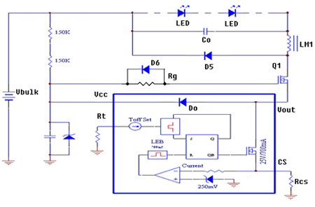
Figure 5: Source drive control electrical principle circuit.
The use of source drive can effectively reduce the current consumption of the drive circuit, reduce power consumption, and improve efficiency. In the traditional high-voltage differential power supply path, in order to reduce the rectified DC high voltage to the low-voltage operating voltage required by the PWM chip, low-resistance and high-power are adopted. The resistor is stepped down, the device is hot, and the power consumption is large.
Isolated and non-isolated LED luminaire drive design applications
BP2808 can also be used to design isolated and non-isolated bulbs, PAR lamps, downlights, recessed lights, garden lights, explosion-proof lights, wall washers, table lamps, work lights, thyristor dimming lights, etc. Drive power. The design principle of non-isolated luminaires can be extended by the above-mentioned typical design ideas of LED fluorescent lamps, and the arrangement of LED light source arrays can be changed into various different types of LED luminaires, which are different for various LED luminaires. It is required to change the output characteristics of the power supply to meet different needs. For example, the thyristor dimming control can use the brain on the application circuit to increase the extraction of the conduction angle information line in the phase-cut power supply, and control the driving current of the LED light source according to the signal to obtain the dimming effect.
The LED fluorescent lamp using BP2808 has entered the “Shanghai Eco-Home†of the 2010 Shanghai World Expo, the Shanghai Metro Station Line 2 of the Shanghai Metro Line 2 and the lighting system of the Malaysian Royal Palace. The BP2808 thyristor dimming isolation and non-isolation scheme for LED lamps such as PAR lamps and bulbs for AC/DC is also mature. The application circuits, PCB boards and BOMs that can be used for production are also available for customers. Enjoy.
Summary of this article
BP2808's fixed Toff working mode, 100% duty cycle, chip operating current reduced to 0.2mA, efficiency of 92%, constant current accuracy, making it more suitable for the application of LED lighting fixtures. In addition to inheriting and absorbing the advantages of similar products at home and abroad, BP2808 adopts an innovative topology, which has significant improvements in chip design and improved performance. In particular, the patent application circuit of constant current compensation and source drive makes BP2808 The application is more convenient and energy efficient.
The LED light source array is designed as a 0.06W white LED (SMT or straw hat) with 24 series and 12 series parallel schemes, driving 288 low power WLEDs with a total power of 18W. The design circuit of the constant voltage source of the full voltage 18W LED fluorescent switch is shown in Figure 2. The functions of each part are marked by the red letter. The anti-lightning and EMI filtering in the figure constitutes an EMC circuit, and the feed current is realized by using a rectifying diode that has been implemented inside the chip.
An automatic Hand Dryer is a sanitary ware appliance for drying or drying hands in the bathroom. It is divided into an induction type automatic hand dryer and a manual hand dryer. The working principle of the hand dryer is generally that the sensor detects a signal (hand). This signal is controlled to turn on the heating circuit relay and the blowing circuit relay to start heating and blowing. When the signal detected by the sensor disappears, the contact is released, the heating circuit and the blowing circuit relay are disconnected, and the heating and blowing are stopped.
It overcomes the shortcomings of the Wall Mounted Hand Dryer that the air can not be discharged in multiple directions and the skin temperature of the hands is too high. It aims to provide a hand dryer that circulates the air in multiple directions. An air guiding device, the air guiding device is provided with air guiding blades, and the rotation of the air guiding device or the swinging of the air guiding blades causes the High Speed Hand Dryer to circulate and not direct the wind.
Automatic hand dryers are advanced and ideal sanitary cleaning appliances and equipment. It is mainly used in hotels, restaurants, scientific research institutions, hospitals, public entertainment venues and the toilets of each family. After washing your hands, put your hands under the air outlet of the automatic hand dryer, the automatic hand dryer will automatically send out comfortable warm air, and quickly make your hands wet and dry, and when you leave the air outlet of the automatic hand dryer When it automatically shuts down the wind again. It can meet the requirements of not drying hands with towels and preventing cross infection of diseases.

Hand Dryer
Quiet Hand Dryers,Touchless Hand Dryer,High Speed Hand Dryer,Wall Mounted Hand Dryer
Taishan Jie Da Electrical Co., Ltd , https://www.ts-jieda.com